Device and method for measuring out-of-plane tensile mechanical property of composite material

A composite material and external stretching technology, which is applied in the direction of measuring devices, using stable tension/pressure to test the strength of materials, and analyzing materials, can solve problems such as low stiffness, thermal stress matching, and poor alignment, and achieve Less equipment investment, lower thermal expansion coefficient, and lower manufacturing cost

Active Publication Date: 2021-10-19
BEIJING INSTITUTE OF TECHNOLOGYGY
View PDF6 Cites 0 Cited by
  • Summary
  • Abstract
  • Description
  • Claims
  • Application Information

AI Technical Summary

Problems solved by technology

[0004] The purpose of the present invention is to provide a device and method for measuring the out-of-plane tensile mechanical properties of composite materials, so as to solve the problem of low rigidity, poor alignment, thermal stress matching be...

Method used


Image

  • Device and method for measuring out-of-plane tensile mechanical property of composite material
  • Device and method for measuring out-of-plane tensile mechanical property of composite material
  • Device and method for measuring out-of-plane tensile mechanical property of composite material

Examples


Embodiment 1

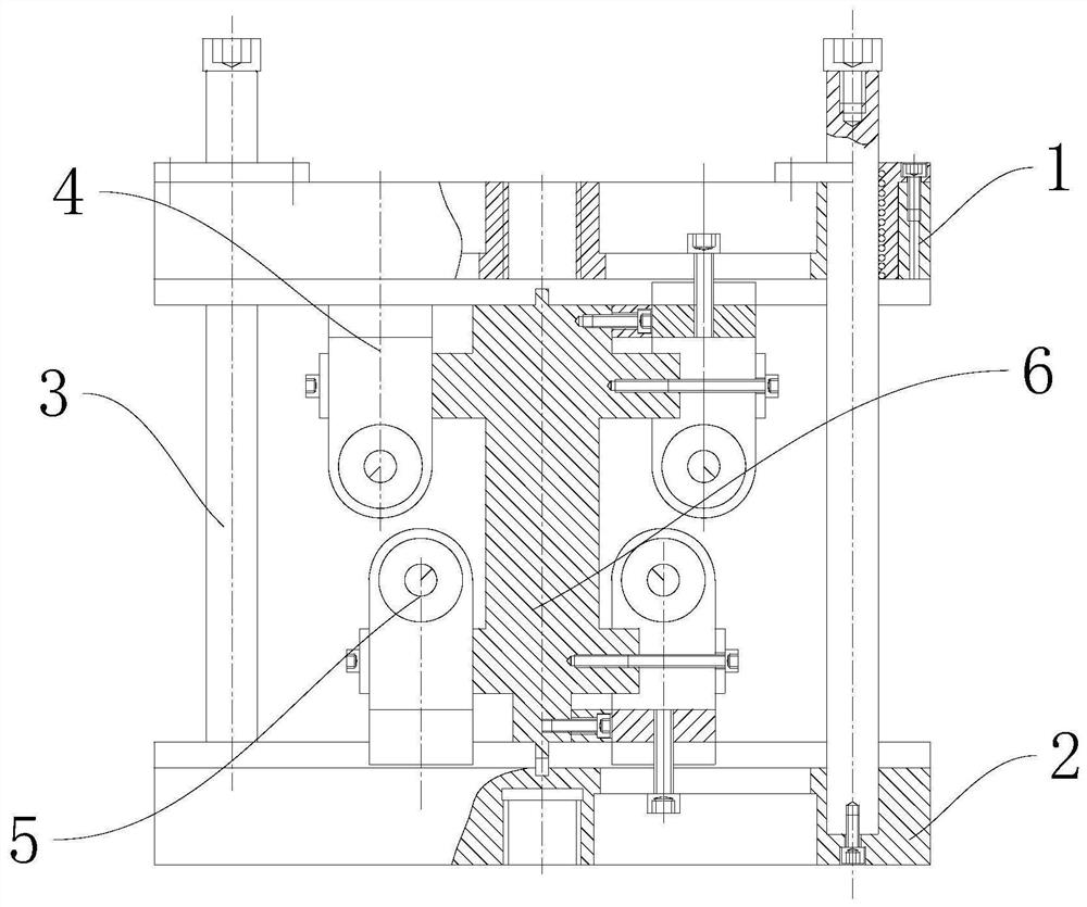
[0040] see Figure 1-7 , a device for measuring out-of-plane tensile mechanical properties of composite materials, including an upper beam 1 and a lower beam 2, the lower beam 2 is arranged at the bottom of the device body, and a guide column is connected to the upper beam 1 and the lower beam 2 3. The bottom end of the guide column 3 is fixedly connected with the lower beam 2, and the upper beam 1 is connected to the guide column 3 by sliding fit; the lower end of the upper beam 1 is connected with the gantry upper pressure roller assembly 4, and the upper end of the lower beam 2 is connected with the gantry frame The lower pressure roller assembly 5, the upper pressure roller assembly 4 of the gantry frame and the lower pressure roller assembly 5 of the gantry frame are connected with an accessory spacer assembly 6.

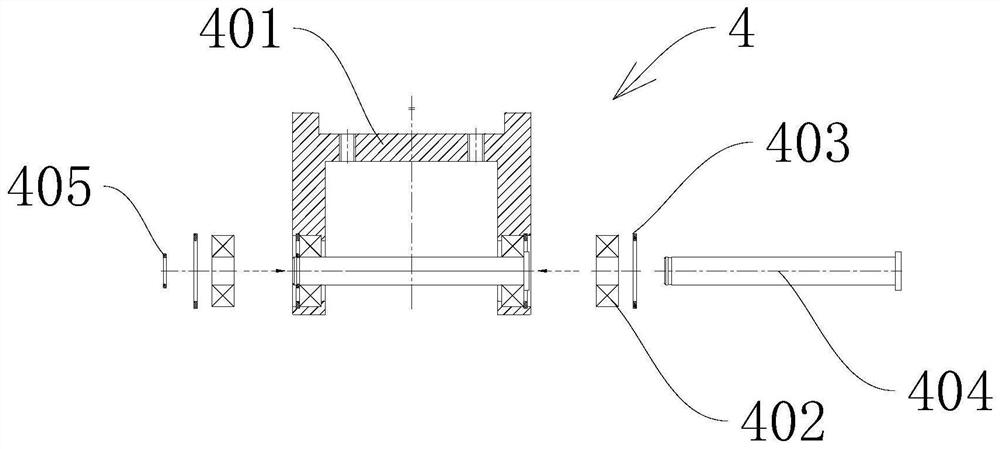
[0041] The upper pressure roller assembly 4 of the gantry frame includes an upper gantry frame 401, which is fixedly installed on the lower end of the upper be...

Embodiment 2

[0065] see Figure 1-7 , based on Embodiment 1, the difference is that;

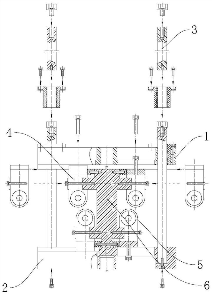
[0066] A biaxially oriented mechanical loading device (such as figure 1 Shown), this device is mainly by lower beam 2, upper beam 1, guide post 3, pressure roller assembly 4 on the gantry frame, pressure roller assembly 5 under the gantry frame, annex spacer assembly 6 to form. The upper pressure roller assembly 4 of the gantry frame and the lower pressure roller assembly 5 of the gantry frame can be freely adjusted in the left and right 50-160mm (test span) along the upper beam 1 and the lower beam 2 upper dark groove as required.

[0067] figure 2 Diagram of the assembly procedure for the device body. First there is a longitudinal groove in the middle part of the upper beam 1, and this side of the transverse boss is facing down, and the rectangular hole in the middle is aligned with the rectangular boss at the upper end of the accessory spacer assembly 6, and is installed on the annex spacer assemb...


PUM

PropertyMeasurementUnit
Glass transition temperatureaaaaaaaaaa

Abstract

The invention discloses a device and a method for measuring out-of-plane tensile mechanical properties of a composite material, and belongs to the technical field of material performance detection. The device and method for measuring the out-of-plane tensile mechanical properties of the composite material comprises an upper beam and a lower beam, the lower beam is arranged at the bottom end of a device body, the upper beam and the lower beam are connected with guide columns, the bottom ends of the guide columns are fixedly connected with the lower beam, and the upper beam is connected to the guide columns in a sliding fit mode; the lower end of the upper beam is connected with a portal frame upper compression roller assembly, the upper end of the lower beam is connected with a portal frame lower compression roller assembly, and an accessory distance frame assembly is connected between the portal frame upper compression roller assembly and the portal frame lower compression roller assembly; and the problems that a metal clamp is low in rigidity and poor in centering performance at high temperature, and thermal stress matching exists between a compression roller and a sample are solved.

Description

technical field [0001] The invention relates to the technical field of material performance detection, in particular to a device and method for measuring out-of-plane tensile mechanical properties of composite materials. Background technique [0002] Thick-section composites are expensive, and full-scale measurement is time-consuming and labor-intensive. It is necessary to propose a reliable test method to characterize the mechanical behavior of thick-interface composites. At present, ASTM and MIL-HDBK-17A have proposed sufficient specifications and testing guidelines for the in-plane properties of composite materials, but there is no reliable experimental method for the characterization of the mechanical properties of composite materials along the out-of-plane direction. As the use of thick-section composite laminates increases year by year, for example, composite blades, composite hydraulic actuators, composite bearings, etc. have obvious compressive stress along the thick...

Claims


Application Information

Patent Timeline
IPC IPC(8): G01N3/08G01N3/18G01N3/02
CPCG01N3/08G01N3/18G01N3/02G01N2203/0003G01N2203/0017G01N2203/0222G01N2203/0226
Inventor 刘刘郝自清韩秀霞邓琳琳王晓宇刘献冲
Owner BEIJING INSTITUTE OF TECHNOLOGYGY
Why Eureka
Try Eureka