Optimization method of heating network model based on topology transformation of heating pipeline network

A technology for heating pipelines and network topology, applied in the field of combined electric-heating dispatch models, can solve problems such as difficulty in applying multi-agent privacy protection, inability to provide physical information parameters, and increased communication burden in the dispatch process, so as to reduce the complexity of the solution and increase the operation. Flexibility, the effect of simplifying scheduling problems

Active Publication Date: 2022-06-03
CHINA THREE GORGES UNIV
View PDF7 Cites 0 Cited by
  • Summary
  • Abstract
  • Description
  • Claims
  • Application Information

AI Technical Summary

Problems solved by technology

Since the full physical model of the heating network is privately owned by each heating company, the physical information parameters required for the node model of the heating network in the combined electricity and heat dispatching cannot be provided to the power system operator or other heating companies, so that centralized electricity and heating combined scheduling cannot be performed
Algorithms such as Benders decomposition algorithm and alternating direction multiplier method are often used in the existing technology to calculate the electricity and heat subjects separately. Although the interaction privacy problem between the electricity and heat subjects is solved, it is difficult to apply to different heat companies in the heat system. The above-mentioned coordinated scheduling method will also increase the communication burden of the scheduling process and reduce the solution efficiency
On the other hand, the heating area of ​​a single heating company can reach several hundred to tens of millions of square meters, and the heating pipe network can reach tens to hundreds of kilometers. In the middle, the large-scale pipeline model will generate a huge amount of constraints on the state of the heating network, which makes the solution of the scheduling model complex

Method used


Image

  • Optimization method of heating network model based on topology transformation of heating pipeline network
  • Optimization method of heating network model based on topology transformation of heating pipeline network
  • Optimization method of heating network model based on topology transformation of heating pipeline network

Examples


Embodiment 1

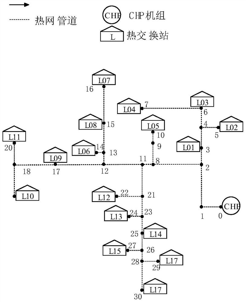
[0217] The district heating system using 30 pipes as shown in Figure 2, and its pipe parameters are shown in Table 1.

[0219]

[0220]

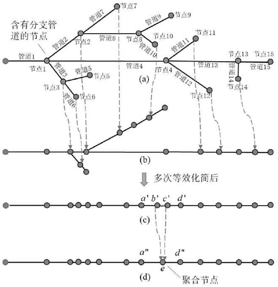
[0222] Model 1: Zone 1 original heat network model with 30 pipes and 17 loads.

[0223] Model 2: Equivalent unbranched model with 30 pipes.

[0224] Models 3-7: Approximate equivalent models when the reduction threshold E is equal to 15, 10, 8, 6, 5.

[0227]

[0228]

[0229] The above simplification results can improve the complexity and privacy of the scheduling process. On this basis, it is also necessary to consider whether the

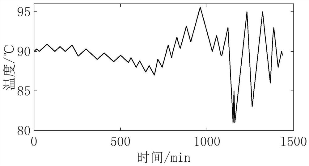
[0230] Figures 4(a) to 4(f) are the return temperatures of each model at the heat source, and the temperature in the red box in Figure 4(a) is not

[0232]

[0233] Table 3 presents the error comparison of each model, because the errors in Fig. 4(a) to Fig. 4(f) oscillate between positive and negative,

[0236]

Embodiment 2

[0238] Using 1 IEEE-30 Node Power System and 2 30 Node District Heating Systems to Build Electric Heating Integrated Energy

[0240]

[0242]

[0244]

[0245] Table 8 load of each node of heat network

[0246]

[0247]

[0249] Figures 10(a) to 10(b) show the optimal heat output of the units of Model 1 and Model 5. The simplified model of the heat network for the unit

[0251]


PUM


Abstract

The heating network model optimization method based on the topology transformation of the heating pipeline network includes: calculating the delay of the working medium transmission time of the branch pipelines at each node of the heating pipeline network; Merge in series into one pipeline; calculate the pipeline parameters of each pipeline after merging; judge whether there are branch pipelines in the heating pipeline network, if so, repeat the previous steps, if not, then set the simplification threshold; remove nodes at both ends The pipelines flowing out of the branch pipelines are aggregated into a new node; the pipeline parameters of each pipeline after aggregation are calculated; it is judged whether the number of pipelines is less than or equal to the simplification threshold E, and if it is less than or equal to E, the heating pipeline network model that finally meets the simplification requirements is obtained , if not satisfied, repeat the previous steps. The invention realizes the simplification of the heating network, reduces the data dimension of the heating network model in the electric-heat joint dispatching, can effectively reduce the solution complexity of the large-scale electric-heat joint dispatching, and improves the solution efficiency.

Description

Optimization method of heating network model based on network topology transformation of heating pipeline technical field The present invention relates to the technical field of electric-heat joint dispatching model, be specifically related to a kind of topology change based on heating pipeline network. The optimization method of the heating network model for the exchange. Background technique [0002] In recent years, under the leadership of the national plan of "developing new energy vigorously" and "promoting central heating", my country's "Three Norths" (Northeast China, North China, Northwest China) is forming an energy structure with a high proportion of wind power and a high proportion of cogeneration units. Uncertainty The serious wind curtailment problem caused by wind power output and cogeneration units in the heat constant power mode makes the traditional deterministic power-heat separation The operating system begins to shift to an integrated electric-ther...

Claims


Application Information

Patent Timeline
Patent Type & Authority Patents(China)
IPC IPC(8): G06F30/18G06F30/17G06F30/20G06Q50/06G06F111/04G06F113/14G06F119/08
CPCG06F30/18G06F30/17G06F30/20G06Q50/06G06F2111/04G06F2113/14G06F2119/08Y02E10/76
Inventor 张磊马宇飞向紫藤叶婧岳东张赟宁黄悦华李振华刘颂凯杨楠张涛薛田良程江洲
Owner CHINA THREE GORGES UNIV
Why Eureka
Try Eureka