Eureka AIR delivers breakthrough ideas for toughest innovation challenges, trusted by R&D personnel around the world.

Circumferential weld narrow gap MAG welding process simulation and molten pool information acquisition device and method

A welding process and simulation device technology, applied in welding equipment, welding accessories, arc welding equipment, etc., can solve the problem that the flow behavior of the molten pool cannot be accurately seen in the transition of the droplet, and the molten pool and sidewall in the groove cannot be truly reflected. Welding conditions, obstacles to the study of the dynamic behavior of the molten pool in the narrow gap welding process, etc., to avoid unfused defects, optimize the groove size, and optimize the experimental design.

Pending Publication Date: 2021-10-22
JIANGSU XCMG CONSTR MASCH RES INST LTD
View PDF7 Cites 2 Cited by
  • Summary
  • Abstract
  • Description
  • Claims
  • Application Information

AI Technical Summary

Problems solved by technology

The first is to directly observe the flow of the molten pool in the groove through the coaxial or side-axis method, but due to the limitation of the groove and the shielding of the molten droplet and the molten pool by the welding torch, it is impossible to accurately see the molten droplet transition and molten pool flow behavior
Another way is to use plate surfacing welding to replace the real welding situation. Although it gets rid of the space limitation, it is quite different from the real welding situation and cannot truly reflect the welding situation between the molten pool and the side wall in the groove
The shortcomings of these methods have greatly hindered the study of the narrow gap welding process and its dynamic behavior of the molten pool, and also made the optimization of process parameters difficult.

Method used


Image

  • Circumferential weld narrow gap MAG welding process simulation and molten pool information acquisition device and method
  • Circumferential weld narrow gap MAG welding process simulation and molten pool information acquisition device and method
  • Circumferential weld narrow gap MAG welding process simulation and molten pool information acquisition device and method

Examples


Embodiment 1

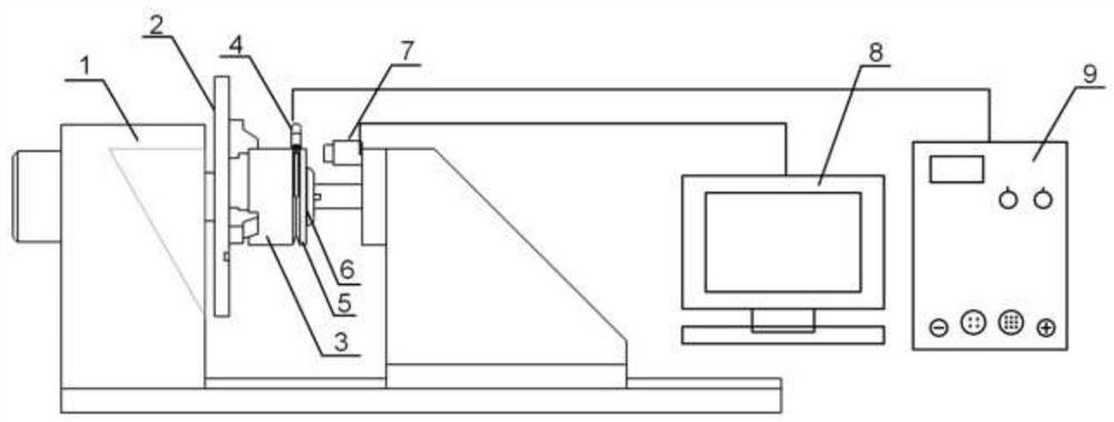
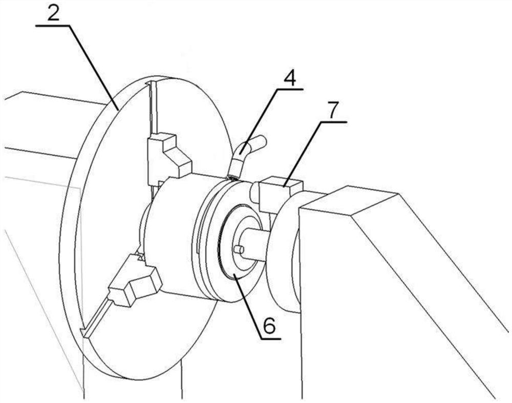
[0028] Such as figure 1 , figure 2 As shown, a girth weld narrow-gap MAG welding process simulation device includes: a workbench 1, on which a first fixture 2 and a second fixture 6 that can rotate coaxially; fixed on the first fixture 2 The metal test piece 3, one surface of the metal test piece 3 is provided with a designated welding groove; There is a specified welding groove, and forms a weld with the welding groove on the metal test piece 3; MAG welding machine 9 is used to perform simulated welding operations on the weld.

[0029] In this embodiment, the first fixture 2 is a three-jaw fixture; the second fixture 6 is a vacuum suction cup; the driving mechanism on the workbench 1 drives the three-jaw fixture to rotate, and the metal test piece 3 is clamped on the three-jaw fixture and The three-jaw clamp rotates coaxially and drives the transparent plate 5 to rotate. The light-transmitting plate 5 is GG17 high-temperature glass, through which the entire dynamic proces...

Embodiment 2

[0032] Such as figure 1 , figure 2 As shown, based on the simulation device for the narrow gap MAG welding process of the girth weld described in the first embodiment, this embodiment provides a melting pool characteristic information collection device for the narrow gap MAG welding process of the girth weld, including: The girth weld narrow-gap MAG welding process simulation device described above; the industrial camera 7 is installed on the workbench 1, and is used to collect the image information of the molten pool in the process of welding the weld seam by the MAG welding machine through the light-transmitting plate 5; the data The processing system 8 is configured to receive and process the image information of the molten pool collected by the industrial camera 7 to obtain characteristic information of the molten pool.

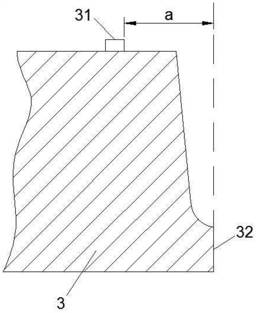
[0033] In this embodiment, the contact between the metal test piece 3 and the GG17 high-temperature glass is processed into a narrow-gap groove that si...

Embodiment 3

[0040] Based on the simulation device for the narrow-gap MAG welding process of the girth weld described in Embodiment 1 and the melting pool characteristic information collection device for the narrow-gap MAG welding process of the girth weld described in Embodiment 2, this embodiment provides a ring The use method of the molten pool feature information collection device in the narrow gap MAG welding process of the weld seam includes: installing the metal specimen with the welded groove on the first fixture; installing the light-transmitting plate with the welded groove on the second on the fixture, and fit the light-transmitting plate and the metal test piece together, so that the welding groove on the metal test piece and the welding groove on the light-transmitting plate form a weld; install the welding torch of the adjusted MAG welding machine At the position of the weld; start the debugged industrial camera and data processing system; start the MAG welding machine to weld...


PUM


Abstract

The invention discloses a circumferential weld narrow gap MAG welding process simulation and molten pool information acquisition device and method in the technical field of welding. The circumferential weld narrow gap MAG welding process simulation device comprises: a workbench, wherein a first clamp and a second clamp which can coaxially rotate are arranged on the workbench; a metal test piece which is fixed on the first clamp, wherein a specified welding groove is formed in one surface of the metal test piece; a light-transmitting plate which is fixed on the second clamp, wherein a specified welding groove is formed in one surface, attached to the metal test piece, of the light-transmitting plate, and the light-transmitting plate and the welding groove in the metal test piece form a welding seam; and an MAG welding machine which is used for carrying out simulation welding operation on the welding seam. The narrow-gap circumferential weld is simulated through the metal test piece with the welding groove and the light-transmitting plate, the whole welding process can be simulated truly, internal changes of a welding pool can be observed conveniently, and conditions are created for studying dynamic behaviors of the welding pool and optimizing MAG welding parameters.

Description

technical field [0001] The invention belongs to the field of welding technology, and in particular relates to a device and method for simulating a girth weld narrow gap MAG welding process and collecting molten pool information. Background technique [0002] In recent years, large-thickness welding products have been widely used in large-scale equipment such as ships and heavy machinery, but welding problems in the manufacturing process have gradually become prominent. Traditional welding methods often use large V-shaped grooves, which seriously affect the progress of engineering production due to problems such as large welding filling volume, low efficiency, and difficult deformation control. One of the key technologies. [0003] The narrow gap MAG welding method, as a welding method that can greatly reduce the groove area and achieve high-efficiency and high-quality welding with a small welding input energy, has become a very potential welding method to solve the welding ...

Claims


Application Information

Patent Timeline
Patent Type & Authority Applications(China)
IPC IPC(8): B23K9/173B23K9/32
CPCB23K9/173B23K9/32
Inventor 彭根琛张立平纪昂
Owner JIANGSU XCMG CONSTR MASCH RES INST LTD
Why Eureka
Eureka Blog
Learn More