A printing flattening device for textile fabrics

A textile fabric and printing technology, which is applied in the field of textile processing, can solve the problems of uneven fabric surface wrinkles, ink accumulation, lack, etc., to achieve the effects of avoiding ink accumulation, improving the smoothing effect, and improving the printing effect

Active Publication Date: 2021-11-30
南通寝尚纺织品有限公司
View PDF17 Cites 0 Cited by
  • Summary
  • Abstract
  • Description
  • Claims
  • Application Information

AI Technical Summary

Problems solved by technology

[0005] Based on the fact that the currently used printing machines lack fabric smoothing devices, the surface of the printed fabric will be wrinkled and uneven, resulting in unclear patterns and ink accumulation after printing, which will affect the overall effect of the fabric. Invention proposes a printing flattening device for textile fabrics

Method used


Image

  • A printing flattening device for textile fabrics
  • A printing flattening device for textile fabrics
  • A printing flattening device for textile fabrics

Examples


Embodiment 1

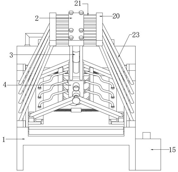
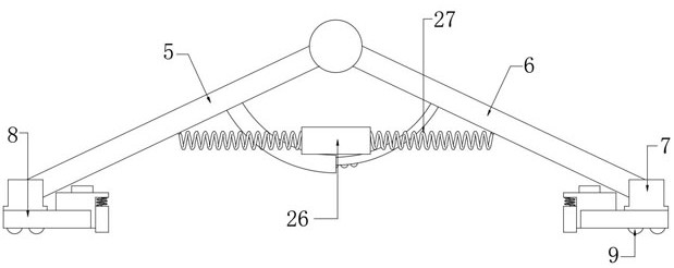
[0033] A printing flattening device for textile fabrics, such as figure 1 and figure 2 As shown, including the outer box 1, one side of the outer box 1 is set as an inclined plane, and a top platform 2 is arranged above the inclined surface, and the bottom of the top platform 2 is provided with a circular groove, and the inner wall of the circular groove is connected with a first bolt. Hydraulic rod 3, the other end of the first hydraulic rod 3 is connected with the processing box 4 by bolts, and the two ends of the processing box 4 are provided with a left strut 5 and a right strut 6, between the left strut 5 and the right strut 6 Connected by bearing rotation, and the bottom ends of the left pole 5 and the right pole 6 are connected with a connection block 7 by bolts, a smoothing assembly is arranged below the connection block 7, and a dust suction assembly is provided on the processing box 4.

[0034] Further, such as image 3 As shown, the smoothing assembly includes a ...

Embodiment 2

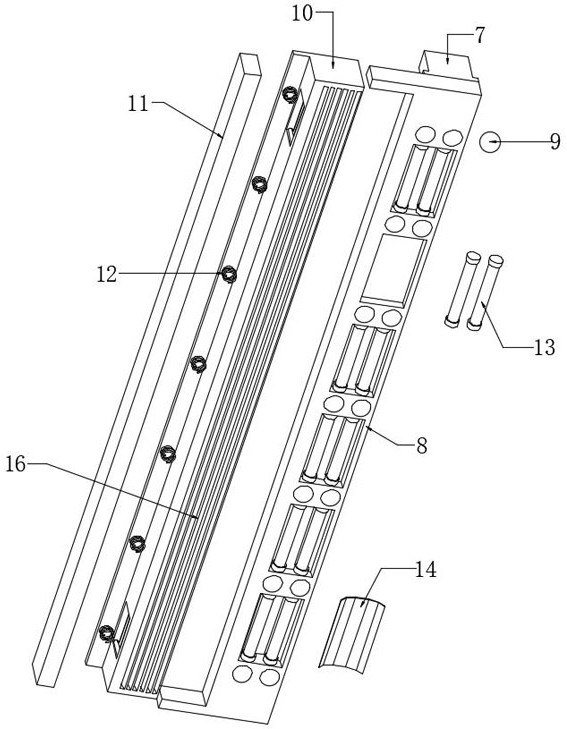
[0036] Further, such as figure 1 , image 3 and Figure 4 As shown, the dust suction assembly includes a vacuum cleaner 15, a dust suction strip 16 and an air inlet 17, the vacuum cleaner 15 is connected with one side of the outer wall of the outer box 1 by bolts, the air inlet 17 is connected with the inner wall of the processing box 4 by bolts, and the dust suction strip 16 and the bottom inner wall of the functional box 10 are connected by bolts; the vacuum cleaner 15 is provided with a dust suction port 18, and the dust suction port 18 and the air inlet 17 are connected by a hose, and the functional box 10 and the processing box 4 are connected by bolts There are a plurality of dust suction pipes 19, and the dust on the surface of the cloth is absorbed and removed by the dust suction assembly during the smoothing operation, so as to prevent the dust on the surface of the cloth from affecting the ink printing quality in the subsequent printing operation.

[0037] Going a ...

Embodiment 3

[0039] Going a step further, as in Figure 5 , Figure 6 , Figure 7 and Figure 8 As shown, there are brackets 28 connected by bolts between the two left struts 5 and the right struts 6, the outer wall of one side bracket 28 is connected with a plurality of speed reduction tubes 29 by bolts, and the outer wall of the other side bracket 28 is connected by bolts There are a plurality of insertion rods 30, the insertion rods 30 are slidingly connected with the inner wall of the deceleration cylinder 29, and the inner wall of the deceleration cylinder 29 is provided with a semicircular retaining groove 31, and the outer wall of one side of the insertion rod 30 is equidistantly provided with a plurality of grooves, the grooves The inner wall of the inner wall is slidingly connected with a stopper 32, and the limit spring 33 is connected between the stopper 32 and the inner wall of the groove of the insertion rod 30 by bolts, and the deceleration cylinder 29 and the insertion rod...


PUM


Abstract

The invention belongs to the technical field of textile processing, in particular to a printing and flattening device for textile fabrics, aiming at the lack of a smoothing device for the cloth in the currently widely used printing machines, and the fact that the cloth in the printing operation will have surface wrinkles and unevenness, As a result, the pattern is unclear and the ink is accumulated after printing, which affects the overall effect of the cloth. The following scheme is proposed, including the outer box, one side of the outer box is set as a slope, and a top platform is set above the slope, and The bottom of the top platform is provided with a circular groove, and the inner wall of the circular groove is fixedly connected with the first hydraulic rod. The present invention adopts the method of pressing down to separate the left and right poles of the smoothing assembly, and uses the pressing plate to smooth the surface of the cloth to be processed after being placed, so as to ensure the flatness of the surface of the cloth to be printed, thereby improving the surface of the textile cloth. Printing effect, avoiding ink accumulation and unclear patterns caused by wrinkles on the surface of the fabric during printing.

Description

technical field [0001] The invention relates to the technical field of textile processing, in particular to a printing flattening device for textile fabrics. Background technique [0002] The original meaning of textile is taken from the general term of spinning and weaving, but with the continuous development and improvement of the textile knowledge system and subject system, especially after the emergence of non-woven textile materials and three-dimensional composite weaving technologies, it is not only the traditional hand spinning And weaving, also including non-woven fabric technology, modern three-dimensional weaving technology, modern electrostatic nano-netting technology and other clothing, industrial and decorative textiles. [0003] During the production and processing of textile fabrics, in order to improve the use effect of the fabrics, the surface of the fabrics will be printed to improve the appearance of the finished fabrics, thereby increasing the sales price...

Claims


Application Information

Patent Timeline
Patent Type & Authority Patents(China)
IPC IPC(8): B41F17/00B41F23/00B65H23/34D06G1/00
CPCB41F23/002B41F17/003B65H23/34D06G1/00B41P2217/50B65H2701/1133
Inventor 魏云
Owner 南通寝尚纺织品有限公司
Why Eureka
Try Eureka