Light partition wall batten mounting structure and preparation method thereof

A light-weight partition wall slat and installation structure technology, which is applied in the direction of walls, ceramic products, manufacturing tools, etc., can solve the problems of low bending load and compressive strength, affecting the stability of the slat connection, troubles, etc., and achieve improvement The effect of installation efficiency

Active Publication Date: 2021-10-22
HAINAN UNIVERSITY
View PDF9 Cites 2 Cited by
  • Summary
  • Abstract
  • Description
  • Claims
  • Application Information

AI Technical Summary

Problems solved by technology

[0005] 1. Although the above-mentioned fixing pin can connect two slats, it cannot make the two slats closely connected when connecting, and still needs to apply adhesive in the later stage, which is troublesome and easy to crack;
[0006] 2. After the above-mentioned fixing pin connects the two slats, it is easy to loosen or fall off during long-term use, which affects the stability of the slat connection and has certain potential safety hazards;
[0007] 3. In the above patents, no improvements have been made to the connection structure between the upper and lower slats. If the fixed pin is applied to the connection between the upper and lower slats, the fixed pin cannot provide a relatively stable longitudinal connection. Under the action of shear force, the fixed pin is easier to loosen and fall off;
[0008] 4. The above-mentioned patents did not improve the composition and preparation method of the slat itself, and did not solve the problems of the slat itself easily cracked, low strength, low bending load and compressive strength;

Method used


Image

  • Light partition wall batten mounting structure and preparation method thereof
  • Light partition wall batten mounting structure and preparation method thereof
  • Light partition wall batten mounting structure and preparation method thereof

Examples


Embodiment 1

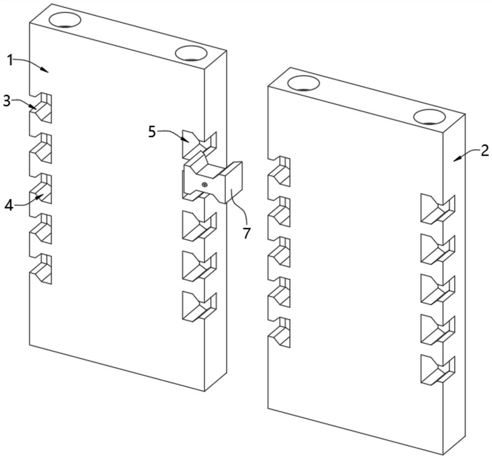
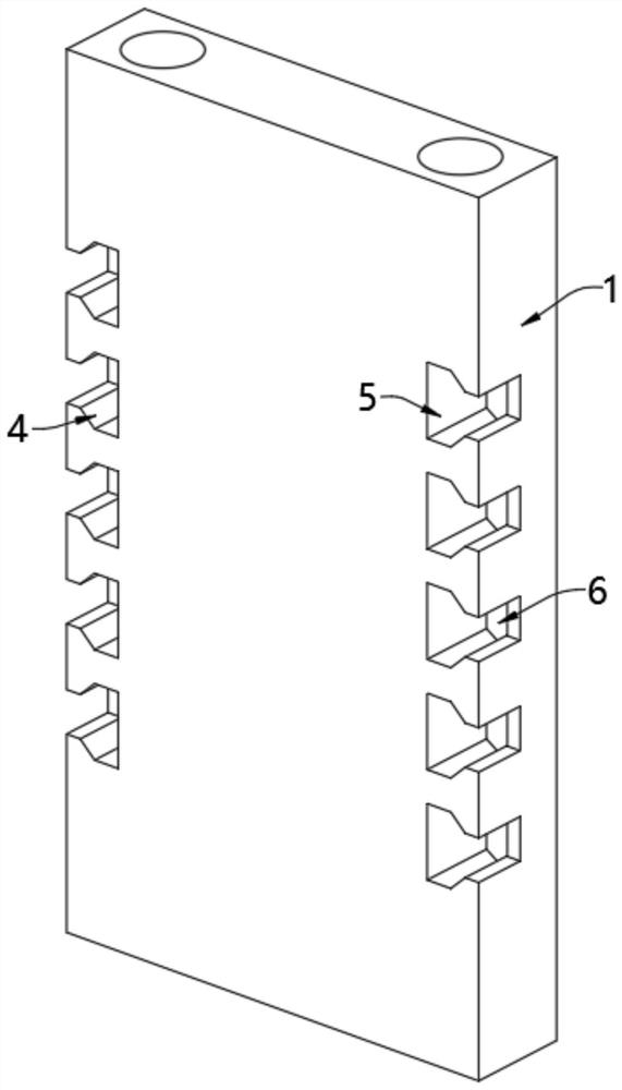
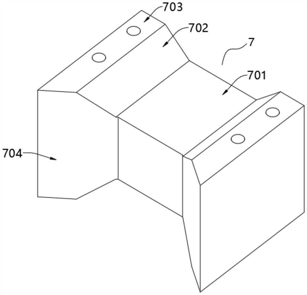
[0068] see Figure 1-Figure 5 , a lightweight partition wall batten installation structure, including a first batten 1 and a second batten 2, both sides of the first batten 1 and the second batten 2 are provided with side grooves 3, and the side grooves 3 face The inner side is provided with a slope groove 4 whose cross section is an isosceles trapezoid, and the inward side of the slope groove 4 is provided with a card groove 5, and the inner walls of the side groove 3, the slope groove 4 and the card groove 5 are movable and provided with a fixed pin 7 , the fixed pin 7 includes a connecting column 701, a slope plate 702 and a clamping plate 703, the two ends of the connecting column 701 are fixedly equipped with a slope plate 702, and the shape of the slope plate 702 matches the shape of the slope groove 4;

[0069] The outer side of the two slope plates 702 is fixedly equipped with a clamping plate 703, and the clamping plate 703 is movably arranged on the inner wall of the...

Embodiment 2

[0074] see Image 6 On the basis of Embodiment 1, vertical grooves 13 are opened inside the two clamping plates 703, and the inner wall of the vertical grooves 13 is movably provided with a first slide plug 15 and a second slide plug 17, and the first slide plug 15 and the second slide plug The outward side of the two sliding plugs 17 is respectively fixed with a first clamping column 16 and a second clamping column 18, and the inner wall of the clamping groove 5 is provided with a locking groove matching the first clamping column 16 and the second clamping column 18. ;

[0075] The control device arranged inside the connecting column 701 and the slope plate 702 makes the first clamping column 16 and the second clamping column 18 extend in and out in the vertical groove 13, and the control device includes a first piston 10, a second piston 11 and a connecting rod. Groove 14, connecting column 701 and slope plate 702 are formed with inner cavity 8, the two ends of inner cavity...

Embodiment 3

[0082] see Figure 7-Figure 10 , on the basis of Embodiment 1 and Embodiment 2, it also includes a third strip 21, the edges of the upper and lower ends of the first strip 1 and the third strip 21 are provided with slots 22, and the two opposite slots A column 23 is inserted between the 22, and the length of the column 23 matches the sum of the depths of the two opposite slots 22;

[0083] The outer wall of the column 23 is covered with a deformable metal column 26, and the upper and lower ends of the deformable metal column 26 are fixedly equipped with a deformable metal plate 27, such as Figure 9 As shown, the deformable metal plate 27 is arranged in a cylindrical shape;

[0084] The outward end of the slot 22 is formed with a trapezoidal groove 24, the inner diameter of the trapezoidal groove 24 gradually decreases from the outside to the inside, and the edge of the inner bottom wall of the trapezoidal groove 24 is provided with a wing groove 25, and the wing groove 25 is...


PUM


Abstract

The invention relates to the technical field of partition wall battens, and discloses a light partition wall batten mounting structure and a preparation method thereof. The light partition wall batten mounting structure comprises a first batten and a second batten, side grooves are formed in the two sides of the first batten and the two sides of the second batten correspondingly, slope grooves with the cross sections being isosceles trapezoids are formed in the inward sides of the side grooves, clamping grooves are formed in the inward sides of the slope grooves, and fixing pins are movably arranged on the inner walls of the side grooves, the slope grooves and the clamping grooves. When the first batten and the second batten are connected, the fixing pins are embedded in the side grooves, the slope grooves and the clamping grooves in the opposite sides of the first batten and the second batten, slope plates and clamping plates on the two sides of the fixing pins are embedded in the slope grooves and the clamping grooves of the first batten and the second batten correspondingly and connected through connecting columns, and under blocking of the side grooves, the slope plates and the clamping plates cannot be transversely separated from the first batten and the second batten, connection is very convenient, and the installation efficiency is greatly improved.

Description

technical field [0001] The invention relates to the technical field of partition wall slats, in particular to a light-weight partition wall slat installation structure and a preparation method thereof. Background technique [0002] Partition wall slats are a new type of energy-saving wall material. As the main material for non-load-bearing inner partition walls in general industrial buildings, residential buildings, and public construction projects, they have many advantages such as light weight, high strength, multiple environmental protection, thermal insulation, and fire prevention. . Existing partition wall slats are usually clamped by grooves and protrusions at both ends of the slats, and then coated with caulking agent. Although this installation structure is convenient and fast, this connection method will cause problems between the slats when used later. There will be a large number of vertical cracks at the joints, which will affect people's normal use, and in seri...

Claims


Application Information

Patent Timeline
Patent Type & Authority Applications(China)
IPC IPC(8): E04B2/74E04B2/82E04B1/94E04B1/92C04B28/10C04B38/00B28B3/00B28B3/20B28B11/12C04B111/40
CPCE04B2/7401E04B2/7403E04B2/82E04B1/942E04B1/92C04B28/10B28B3/00B28B3/20B28B11/12C04B2111/40C04B7/00C04B14/06C04B14/28C04B24/383C04B2103/42C04B38/00
Inventor 孙涛叶建强
Owner HAINAN UNIVERSITY
Why Eureka
Try Eureka