Indoor SLAM mapping method based on 3D laser radar and UWB

A laser radar and 3D technology, applied in 3D modeling, image enhancement, image analysis, etc., can solve problems such as the inability to eliminate SLAM cumulative errors, visual camera limitations, etc., to save manpower and time, improve positioning accuracy and robustness , to avoid the effect of manual measurement

Active Publication Date: 2021-10-22
GUANGDONG UNIV OF TECH
View PDF7 Cites 2 Cited by
  • Summary
  • Abstract
  • Description
  • Claims
  • Application Information

AI Technical Summary

Problems solved by technology

Indoor environments may be affected by lighting conditions, and the use of visual cameras as sensors may be severely limited; on the other hand, due to occlusion in indoor environments, it is impossible to eliminate SLAM cumulative errors by fusing GPS data

Method used


Image

  • Indoor SLAM mapping method based on 3D laser radar and UWB
  • Indoor SLAM mapping method based on 3D laser radar and UWB
  • Indoor SLAM mapping method based on 3D laser radar and UWB

Examples


Embodiment Construction

[0097] The present invention will be further described below in conjunction with specific embodiment:

[0098] like figure 1 As shown, in the indoor SLAM mapping method based on 3D lidar and UWB described in this embodiment, a UWB positioning system is deployed in an indoor scene, and a robot carrying a 3D lidar sensor is used to explore the indoor scene area. The SLAM algorithm of lidar data and UWB data generates a map of the explored area;

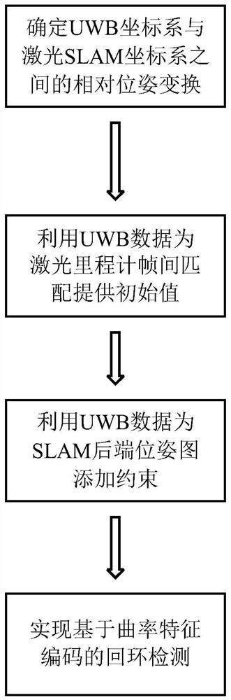
[0099] Specifically include the following steps:

[0100] S1. Determine the relative pose transformation between the 3D laser SLAM coordinate system and the UWB positioning coordinate system;

[0101]In this embodiment, a UWB positioning system is deployed in an indoor scene, and a human or robot carrying a 3D lidar sensor is used to explore the indoor area, and a map of the explored area is generated using a SLAM algorithm that fuses lidar data and UWB data.

[0102] In the UWB positioning system used, there are multiple sensor node...


PUM


Abstract

The invention discloses an indoor SLAM mapping method based on a 3D laser radar and UWB, and the method comprises the steps: deploying a UWB positioning system in an indoor scene, exploring the region of the indoor scene through a robot carrying a 3D laser radar sensor, and generating a map of the explored region through an SLAM algorithm fusing laser radar data and UWB data. The method specifically comprises the following steps: S1, determining relative pose transformation between a 3D laser SLAM coordinate system and a UWB positioning coordinate system; S2, providing an initial value for inter-frame matching of the laser speedometer by using UWB data; S3, using UWB data to add constraints to the SLAM rear-end pose map; and S4, performing loopback detection based on curvature feature coding. According to the method, the illumination condition limitation of an indoor scene is broken through, and the accumulated error of SLAM is eliminated, so that a high-quality indoor map is constructed.

Description

technical field [0001] The present invention relates to the technical field of state estimation and map construction, in particular to an indoor SLAM mapping method based on 3D lidar and UWB. Background technique [0002] Indoor mapping technology has been widely used in modern society, especially in logistics, rescue, military, security and other fields. There are many ways to construct indoor maps, which can be divided from static and dynamic perspectives. [0003] The static method is mainly to statically deploy sensors with ranging functions such as lidar or visual cameras in each sub-area of ​​the current indoor environment in a fixed indoor environment, and use the independent sensor data of each sub-area to construct the The corresponding map; finally, the sub-maps of each sub-region are spliced ​​according to the spatial position relationship of each independent sensor to obtain a complete indoor map. [0004] The static indoor map construction method has the advan...

Claims


Application Information

Patent Timeline
Patent Type & Authority Applications(China)
IPC IPC(8): G06T7/00G06T7/521G06T7/70G06T17/05G01S17/86
CPCG06T7/0002G06T7/521G06T17/05G06T7/70G01S17/86G06T2207/10044G01S17/06G01S17/89G01S13/865G01S13/0209G01S17/42G01S17/894
Inventor 刘建圻王欧宇
Owner GUANGDONG UNIV OF TECH
Why Eureka
Try Eureka