
Optical module

An optical module and laser technology, applied in the field of optical modules, can solve the problems of high manufacturing cost, difficult design, excluding low-noise power supply, etc., and achieve the effect of fast turn-on and turn-off

Active Publication Date: 2021-10-22
HISENSE BROADBAND MULTIMEDIA TECH
View PDF4 Cites 0 Cited by
  • Summary
  • Abstract
  • Description
  • Claims
  • Application Information

AI Technical Summary

Problems solved by technology

However, it is difficult to design a low-noise power supply on the driving circuit in the high-speed EML and the manufacturing cost is high. Therefore, the low-noise power supply is usually not included in the driving circuit in the high-speed EML, and it needs to be designed and connected separately when the EML is used. driven by a low noise power supply

Method used


Image

  • Optical module
  • Optical module
  • Optical module

Examples


Embodiment Construction

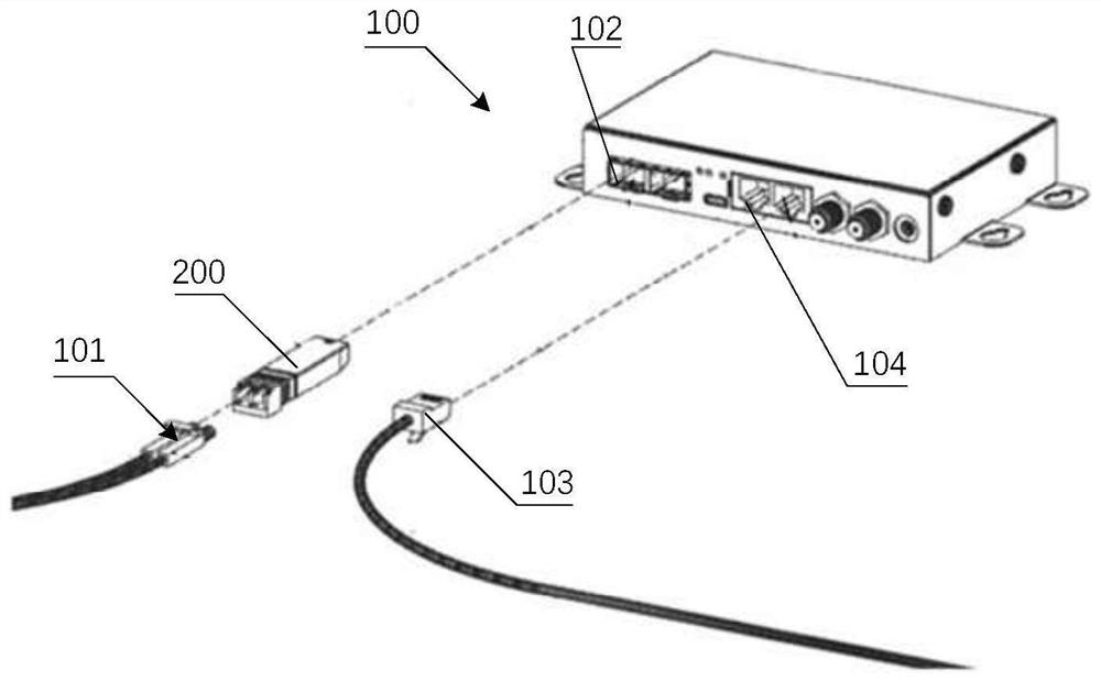
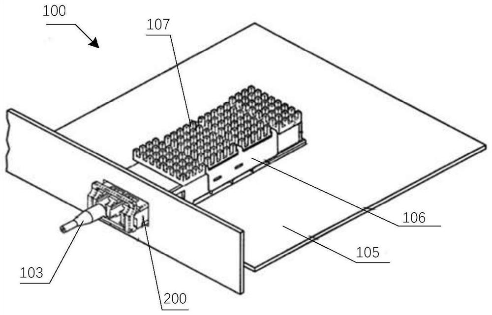
[0026] The following will clearly and completely describe the technical solutions in the embodiments of the present invention with reference to the accompanying drawings in the embodiments of the present invention. Obviously, the described embodiments are only some, not all, embodiments of the present invention. Based on the embodiments of the present invention, all other embodiments obtained by persons of ordinary skill in the art without creative efforts fall within the protection scope of the present invention.

[0027] One of the core links of optical communication is the mutual conversion of optical and electrical signals. Optical communication uses optical signals carrying information to be transmitted in information transmission equipment such as optical fibers / optical waveguides, and the passive transmission characteristics of light in optical fibers / optical waveguides can be used to achieve low-cost, low-loss information transmission; and information processing equipme...


PUM


Abstract

The invention provides an optical module. The optical module comprises a circuit board; a light emitting assembly which is electrically connected with the circuit board and used for generating signal light; an MCU which is arranged on the circuit board and is used for outputting an enabling control signal; a direct-current driving current source which is arranged on the circuit board and outputs direct-current driving current; and an enabling circuit which is arranged on the circuit board, wherein a first input end of the enabling circuit receives an enabling control signal, a second input end of the enabling circuit receives the direct-current driving current, and an output end of the enabling circuit is switched to output the direct-current driving current according to the enabling control signal. The light emitting assembly comprises a laser which emits light not carrying signals when the anode receives the direct-current driving current; and an electro-absorption modulator which is used for modulating and processing the light which does not carry the signal according to the electro-absorption modulation signal to obtain signal light. According to the invention, through the enabling circuit, starting and stopping of light emitting work of the light emitting assembly are realized, rapid starting and stopping of the optical module are realized, and time requirements of an optical module protocol for starting time less than 1mS and stopping time less than 10uS are satisfied.

Description

technical field [0001] The present application relates to the technical field of optical fiber communication, and in particular to an optical module. Background technique [0002] Optical communication technology will be used in new business and application modes such as cloud computing, mobile Internet, and video. In optical communication, the optical module is a tool to realize the mutual conversion of photoelectric signals, and it is one of the key components in optical communication equipment. And with the rapid development of 5G network, the optical module at the core of optical communication has been greatly developed. Among them, for the signal transmission of the optical module, VCSEL (Vertical Cavity Surface Emitting Laser, vertical cavity surface emitting laser), EML (Electlro-absorption Modulated Laser, electro-absorption modulated laser) and other types of signal transmission methods can be used. [0003] As the transmission rate increases, the influence of pow...

Claims


Application Information

Patent Timeline
Patent Type & Authority Applications(China)
IPC IPC(8): H04B10/50H04B10/516
CPCH04B10/503H04B10/50H04B10/516Y02B20/30
Inventor 杨世海杨柳张强赵其圣
Owner HISENSE BROADBAND MULTIMEDIA TECH
Learn More