Eureka AIR delivers breakthrough ideas for toughest innovation challenges, trusted by R&D personnel around the world.

Filling base material type selection method of support plate hole filling process and support plate hole filling process

A carrier plate and substrate technology, which is applied to the filling substrate selection method and the hole filling process field of the carrier plate hole filling process, can solve the problems of affecting the filling efficiency, failure, low efficiency, etc., and achieves improved filling effect and high speed. , the effect of high efficiency

Active Publication Date: 2021-10-22
GUANGDONG UNIV OF TECH
View PDF12 Cites 0 Cited by
  • Summary
  • Abstract
  • Description
  • Claims
  • Application Information

AI Technical Summary

Problems solved by technology

At present, the realization of through hole and blind hole interconnection structure mainly adopts electroplating copper hole filling technology; however, using electroplating solution to fill holes has the following disadvantages: (1) In the process of microhole filling, it is easy to produce Holes, gap filling and other defects; on the one hand, it affects the electrical and thermal conductivity of through holes and blind holes; on the other hand, due to the mismatch of thermal expansion coefficients between copper and substrate materials, it is easy to cause stress concentration, induce cracks and lead to failure
(2) In order to avoid filling defects, the electroplating copper hole filling process needs to use lower current, which affects the filling efficiency; for large-sized holes (>10μm), the electroplating copper hole filling efficiency is extremely low

Method used


Image

  • Filling base material type selection method of support plate hole filling process and support plate hole filling process
  • Filling base material type selection method of support plate hole filling process and support plate hole filling process
  • Filling base material type selection method of support plate hole filling process and support plate hole filling process

Examples


Embodiment 1

[0048] see Figure 1-Figure 3 , this embodiment discloses a filling substrate type selection method for a carrier plate hole filling process, comprising the following steps:

[0049] (1) Determine the size and required performance of the through hole or blind hole on the carrier board 1 .

[0050] (2) Select the appropriate type of filling substrate 5, including nano-metal sintered body, metal block, etc.

[0051] (3) Select the particle size of filling base material 5; Wherein, the particle size of filling base material 5 is selected as follows:

[0052] (a) Small grain filling, D=0.001~0.2d

[0053] (b) String filling, D=0.5d~2d

[0054] (c) Single-grain overall filling, D=0.5(1.5d 2 h) 0.5 ~2(1.5d 2 h) 0.5

[0055] Wherein, in the above formula, D is the particle diameter of the filling substrate 5, d is the diameter of the through hole or blind hole on the carrier plate 1, and h is the depth of the through hole or blind hole on the carrier plate 1.

[0056]When th...

Embodiment 2

[0067] This embodiment discloses a specific example of the type selection method for the filling base material 5 in Embodiment 1. specifically,

[0068] (1) The size of the through hole to be filled on the carrier plate 1: the diameter d is 300 nm, and the depth h is 800 nm.

[0069] (2) A nano-silver sintered body is selected as the filling base material 5 .

[0070] (3) Select string filling, that is, D=0.5d~2d; the selected particle size is 150nm~600nm.

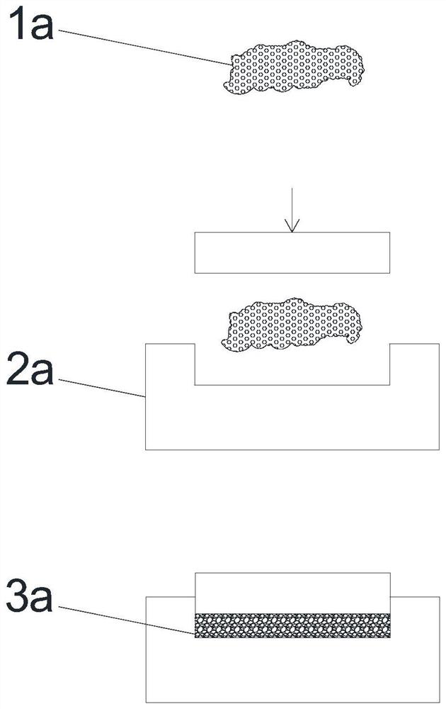
[0071] see figure 1 , for the filling base material 5 selected above, the processing method is as follows: the nano-silver particles 1a are pressurized and sintered into a block in a mold 2a with a cross-sectional area of ​​10×10mm under the temperature of 350°C and a pressure of 20MPa to form The metal silver block 3a is used as the filling base material 5 for the hole-filling embossing of the carrier plate 1 .

Embodiment 3

[0073] This embodiment discloses a specific example of the type selection method for the filling base material 5 in Embodiment 1. specifically,

[0074] (1) The size of the through hole to be filled on the carrier plate 1: the diameter d is 20 μm, and the depth h is 100 μm.

[0075] (2) A metal block is selected as the filling base material 5 .

[0076] (3) Choose small grains to fill, that is, D=0.001~0.2d; the selected particle size is 0.02μm~4μm.

[0077] For the filling base material 5 selected above, the processing method is as follows: a copper block with a shape of 10×10×2 mm is passed through a high-frequency current of 30 MHz 5 A to heat the surface of the copper block. Conduct ultrasonic vibration on the copper block, and control the ultrasonic frequency to 2.26×10 under the condition that the surface wave sound velocity of the copper block is 2260m / s 8 Hz, so that the average grain size on the surface reaches 5 μm, thereby making a filling base material 5 of the ...


PUM

PropertyMeasurementUnit
Thicknessaaaaaaaaaa
Particle sizeaaaaaaaaaa

Abstract

The invention discloses a filling base material type selection method of a support plate hole filling process and the support plate hole filling process. The filling base material type selection method comprises the following steps: (1) determining the size and the required performance condition of a through hole or a blind hole in a carrier plate; (2) selecting a proper filling base material type; (3) selecting the particle size of the filling base material, wherein the particle size of the filling base material is selected as follows: (a) small particle filling, D = 0.001-0.2 d, (b) string type filling, D = 0.5-2d, (c) single particle integral filling, D = 0.5(1.5d2h)0.5-2(1.5 d2h)0.5; the D is the diameter of the filler, d is the diameter of the through hole or the blind hole in the carrier plate, and h is the depth of the through hole or the blind hole in the carrier plate. According to the filling base material type selection method, a filling base material type selection scheme is provided for a support plate hole filling technology. According to the method, the hole filling process of the support plate is more perfect, the proper filling base material can be selected according to the required performance of the through holes and the blind holes of the support plate, and the circuit structure performance of the support plate can be improved.

Description

technical field [0001] The invention relates to a hole-filling technology of a circuit carrier, in particular to a filling base material type selection method and a hole-filling process of the carrier-board hole-filling process. Background technique [0002] As one of the core technologies of semiconductor and integrated circuit manufacturing, carrier board hole filling technology can obtain through-hole and blind-hole interconnection structures, which has the advantages of reducing time delay, reducing energy consumption, and improving integration. At present, the realization of through hole and blind hole interconnection structure mainly adopts electroplating copper hole filling technology; however, using electroplating solution to fill holes has the following disadvantages: (1) In the process of microhole filling, it is easy to produce Holes, gap filling and other defects; on the one hand, it affects the electrical and thermal conductivity of through holes and blind holes...

Claims


Application Information

Patent Timeline
IPC IPC(8): H05K3/42
CPCH05K3/421H05K3/423
Inventor 杨冠南姚可夫李泽波崔成强
Owner GUANGDONG UNIV OF TECH
Why Eureka
Eureka Blog
Learn More