Truss type double-wall heat insulation device for engine combustion chamber and cold air film forming method

A technology of heat insulation device and combustion chamber, which is applied in the direction of combustion method, combustion chamber, continuous combustion chamber, etc., can solve problems such as increasing engine life and reducing air flow, reducing cooling pressure, improving life and reliability, and improving effect of life

Pending Publication Date: 2021-10-26
NORTHWESTERN POLYTECHNICAL UNIV
View PDF3 Cites 2 Cited by
  • Summary
  • Abstract
  • Description
  • Claims
  • Application Information

AI Technical Summary

Problems solved by technology

In addition, as the air flow required for mainstream combustion increases, the air flow used for cooling decreases. Therefore, it is necessary to apply a more reasonable structure and a heat shield structure with cooling capacity to increase the life of the engine.

Method used


Image

  • Truss type double-wall heat insulation device for engine combustion chamber and cold air film forming method
  • Truss type double-wall heat insulation device for engine combustion chamber and cold air film forming method
  • Truss type double-wall heat insulation device for engine combustion chamber and cold air film forming method

Examples


Embodiment 1

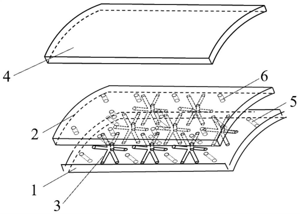
[0030] Embodiment 1: as figure 1 , figure 2 , image 3 Shown, a kind of truss type double-wall thermal insulation device for engine combustion chamber, comprises the gas film orifice plate layer 1 that is used to form the inner wall of the combustion chamber barrel and the impact orifice plate layer on the gas film orifice layer (outside 2. The inner side of the gas film orifice layer 1 is the main gas duct (8) of the combustion chamber, and the impact orifice layer 2 and the outer wall surface 4 of the combustion chamber together form the cold air duct 7; the gas film orifice layer 1 and the impact hole The cavity between the slabs 2 is provided with sandwich Pozierian trusses 3 arranged in a matrix; the air-film orifice plate layer 1, the impact orifice plate layer 2 and the sandwich Pozierian trusses 3 together form a double-wall heat insulation screen;

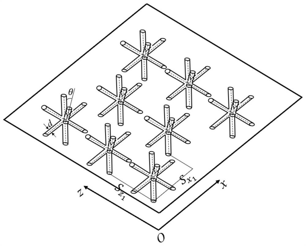
[0031] The sandwich rice-shaped truss 3 is composed of four truss rods, the midpoints of the four truss rods cross ea...

Embodiment 2

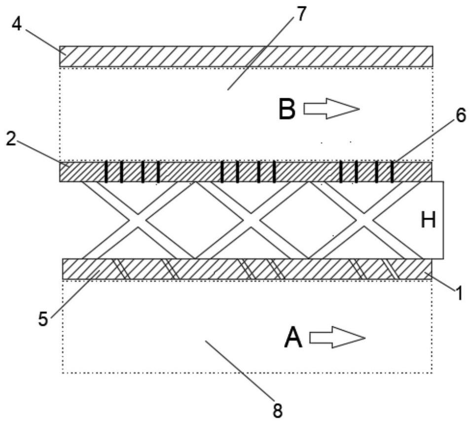
[0040] Embodiment 2: as Figure 4 , Figure 5 As shown, the present invention also provides a method for forming an air film on an air film orifice in a truss type double-wall insulation device for an engine combustion chamber, the steps are as follows:

[0041] Part of the cooling air flow B in the cold air duct 7 is perpendicular to the impact jet C1 of the impact orifice plate 2, and enters the cavity between the air film orifice plate 1 and the impact orifice plate 2 through the impact hole 6 on the impact orifice plate 2 ;

[0042] The impact jet C1 entering the cavity between the air film orifice plate 1 and the impact orifice plate 2 is a part of the impact jet that directly impacts and cools the inner wall of the air film orifice plate 1 to form an impact cooling air flow C3, and the other part impacts the sandwich rice word truss 3, and collide with the surface of the sandwich truss 3 to form a flow C2 around the sandwich truss 3,

[0043] A part of the bypass flow...


PUM


Abstract

The invention relates to a truss type double-wall heat insulation device for an engine combustion chamber. The truss type double-wall heat insulation device comprises a gas film pore plate layer, an impact pore plate layer and a sandwich truss shaped like the Chinese character'mi' which are used for forming the inner wall of a combustion chamber barrel, the sandwich truss shaped like the Chinese character'mi' is composed of four truss rods, the midpoints of the four truss rods are mutually crossed to form a central cross point, two ends of the four truss rods are connected with the impact pore plate and the air film pore layer, air film holes matched with the sandwich truss shaped like the Chinese character'mi' are formed in the air film hole plate, and impact holes matched with the sandwich truss shaped like the Chinese character'mi' are formed in the impact hole plate. The invention further provides a method for forming the cold air film through the device, the air film holes and the impact holes are matched between an air film hole plate layer and an impact hole plate layer to form four strands of longitudinal cooling vortex systems extending in the airflow flowing direction, and an air film cold air heat insulation layer is formed on the outer wall face of the air film hole plate. The structure is simple, the strength is high, the operation temperature of an engine is increased, the service life of the engine is prolonged, and meanwhile the strength is improved.

Description

technical field [0001] The invention belongs to the field of gas turbine engines, and in particular relates to a double-wall heat shield structure with a truss sandwich structure and a cold air film forming method. Background technique [0002] Previously disclosed several combustion chamber heat shields, including a porous corrugated plate combustion chamber heat shield (US005465572A), the stretchability of its corrugated structure can effectively prevent the impact caused by the thermal deformation of the vibrating nuclear cylinder, and through the corrugated plate The cooling jets from the upper discrete film holes perform film cooling on the high temperature gas side of the heat shield. However, it is precisely because of the corrugated structure that it is difficult for the cooling air film jet to cover the entire surface, so that the local wall temperature is too high to form effective air film coverage and heat exchange; the other is the divergent cooling and heat ins...

Claims


Application Information

Patent Timeline
Patent Type & Authority Applications(China)
IPC IPC(8): F23R3/00
CPCF23R3/002F23R2900/03043
Inventor 白晓辉刘存良刘海涌傅松王子文
Owner NORTHWESTERN POLYTECHNICAL UNIV
Why Eureka
Try Eureka