
Portable dust monitor

A monitor and portable technology, applied in the field of portable dust monitors, can solve problems such as manual calibration, instrument drift, optical window pollution, etc., achieve the effects of stabilizing fluid pressure and flow, eliminating gas pressure pulsation, and accurate measurement results

Active Publication Date: 2021-10-26
CHINA UNIV OF MINING & TECH
View PDF16 Cites 0 Cited by
  • Summary
  • Abstract
  • Description
  • Claims
  • Application Information

AI Technical Summary

Problems solved by technology

[0003] At present, the dust monitoring equipment used in mines mostly adopts the principle of light scattering, and its measurement accuracy is greatly affected by changes in environmental temperature, humidity, coal quality and lithology, and the traceability of the value is not good. In the continuous monitoring process, problems such as optical window pollution and instrument drift are likely to occur, resulting in a decrease in measurement accuracy
At the same time, this kind of dust monitoring equipment cannot be calibrated in real time, resulting in insufficient reliability of the final detection results, which cannot meet the real-time monitoring needs of mine personnel
In addition, due to the need for dust reduction in the downhole operation environment, there are often a large number of atomized droplets around the spray dust reduction site or in the wind flow, which will make the accuracy of the detection results in this site unable to be guaranteed, so frequent inspections are required. Carry out manual calibration and post-maintenance
Furthermore, most of the existing monitoring equipment is a fixed structure, which cannot be easily moved, let alone carried around, and cannot complete the real-time measurement of the cumulative dust exposure of miners

Method used


Image

  • Portable dust monitor
  • Portable dust monitor

Examples


Embodiment Construction

[0026] The present invention will be further described below.

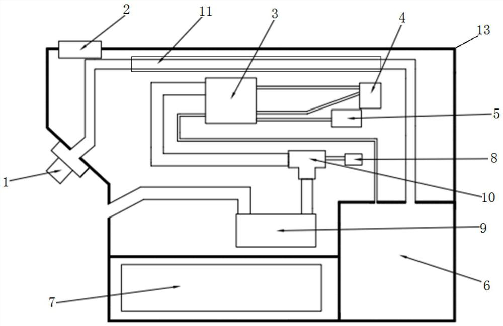
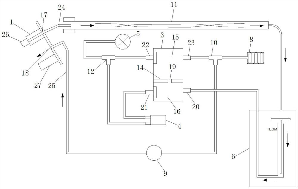
[0027] Such as figure 1 and figure 2 As shown, the present invention provides a portable dust monitor, including a small housing 13, the small housing 13 is provided with a main air inlet 17 and a main exhaust port 18, and also includes a small housing 13 inside Temperature and humidity measuring box 3, dust measuring instrument 6, drying pipeline 11, first three-way pipe fitting 10, pulsation damper 8, vacuum sampling pump 9, environmental pressure sensor 5, differential pressure flowmeter 4, battery pack 7 and controller;

[0028] The middle part of the cavity of the temperature and humidity measurement box 3 is equipped with a partition 14, and the cavity of the temperature and humidity measurement box 3 is isolated by the partition 14 into an upper cavity space 15 and a lower cavity space 16, and the partition 14 The middle part is provided with a strip-shaped communication hole 19 communicating with the u...


PUM


Abstract

The invention discloses a portable dust monitor. A main air inlet and a main air outlet are formed in a small shell. A partition plate and a temperature and humidity sensor are installed in an inner cavity of the temperature and humidity measuring box. A strip-shaped communicating hole is formed in the middle of the partition plate. The outer side of the temperature and humidity measuring box is connected with a first air inlet pipeline, a first air outlet pipeline, a second air outlet pipeline and a third air outlet pipeline. An air outlet and an air inlet of the dust meter are respectively connected with the air outlet ends of the first air inlet pipeline and the drying pipeline; the air inlet end of the drying pipeline is connected with the main air inlet; air inlets of the pulsation damper, the third air outlet pipeline and the vacuum sampling pump are respectively connected with three interfaces of the first three-way pipe fitting; an air outlet of the vacuum sampling pump is connected with the main exhaust port; and the environment pressure sensor, the second air outlet pipeline and a second air inlet of the differential pressure type flow meter are connected with one outlet of the second three-way pipe fitting, and a first air inlet of the differential pressure type flow meter is connected with the first air outlet pipeline. The monitor is convenient to carry and can ensure the credibility of a detection result.

Description

technical field [0001] The invention belongs to the technical field of dust measurement, and in particular relates to a portable dust monitor. Background technique [0002] There is a large amount of dust in most coal mine roadways, coal mining faces and ground tunnel excavation faces, among which the concentration of respirable dust which is harmful to workers seriously exceeds the allowable exposure concentration standard, which makes working in coal mines The incidence of pneumoconiosis among workers remains high, and real-time dust monitoring is the premise and key measure for effective dust prevention and control. [0003] At present, the dust monitoring equipment used in mines mostly adopts the principle of light scattering, and its measurement accuracy is greatly affected by changes in environmental temperature, humidity, coal quality and lithology, and the traceability of the value is not good. During the continuous monitoring process, problems such as optical windo...

Claims


Application Information

Patent Timeline
Patent Type & Authority Applications(China)
IPC IPC(8): G01N15/06G01D21/02G05D7/06
CPCG01N15/0618G01N15/06G01D21/02G05D7/0629G01N2015/0681Y02A50/20
Inventor 郑丽娜冯子康刘凌妤
Owner CHINA UNIV OF MINING & TECH
Learn More