Self-cleaning type diethyltoluenediamine reaction kettle

A technology of diethyltoluenediamine and reactors, applied in chemical/physical/physical chemical fixed reactors, detailed information of chemical/physical/physical chemical reactors, preparation of amino compounds, etc., can solve problems affecting purity, Difficult to stir impeller cleaning and other problems

Active Publication Date: 2021-10-29
东营海瑞宝新材料有限公司
View PDF7 Cites 6 Cited by
  • Summary
  • Abstract
  • Description
  • Claims
  • Application Information

AI Technical Summary

Problems solved by technology

[0002] At present, during the processing of diethyltoluenediamine in the prior art, because aromatic amine catalysts are added to the prepared diethyltoluenediamine stock solution, and these catalyst residues and a small amount of aromatic amine derivatives affect the diethyltoluenediamine The purity of the stock solution of toluenediamine, in order to remove such impurities, other reaction liquids will be added again, resulting in the production of various solid impurities during the reaction process, which will then adhere to the inner wall, wall plate and stirring blade of the reaction kettle. The rinsing, spraying and cleaning solution immersion can only dissolve and separate the thin impurity layer on the inner wall of the reaction kettle. During the solution stirring reaction process, the solution will form a vortex backflow when it touches the wall plate during the rotation process to enhance the stirring and mixing effect. At the same time, the impurities adhering to both sides of the wall plate are also thick, and it is difficult to completely remove the impurities on both sides of the wall plate and the gap between the wall plate and the inner surface of the reactor by soaking in the cleaning solution. Regular head stirring blades, it is difficult to wash and clean the stirring blades in a closed reaction kettle

Method used


Image

  • Self-cleaning type diethyltoluenediamine reaction kettle
  • Self-cleaning type diethyltoluenediamine reaction kettle
  • Self-cleaning type diethyltoluenediamine reaction kettle

Examples


Embodiment 1

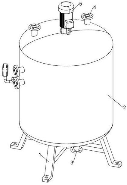
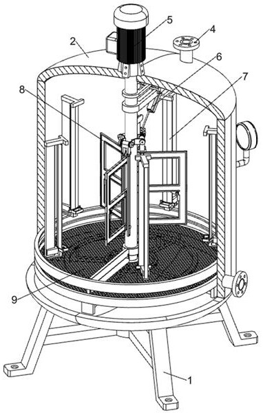
[0036] according to Figure 1-2 As shown, a self-cleaning diethyltoluene diamine reactor includes a bottom support frame 1, a reactor body 2, a liquid outlet valve 3, a liquid inlet valve 4, a mixer head assembly 5, a lifting control system 6, a wall Plate cleaning system 7, machine head cleaning system 8 and crushing system 9; the top of the bottom support frame 1 is welded with the reactor body 2; the middle and front side of the bottom of the reactor body 2 is equipped with a liquid outlet valve 3; the top of the reactor body 2 is left behind A liquid inlet valve 4 is installed on the side and the right rear side; a mixer head assembly 5 is installed in the middle of the reactor body 2; a lifting control system 6 is installed on the front side of the mixer head assembly 5; five Wall plate cleaning system 7; three machine head cleaning systems 8 are equidistantly installed on the outer ring surface of the lower part of the mixer head assembly 5;

[0037] During the normal p...

Embodiment 2

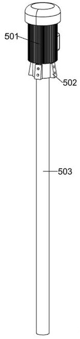
[0039] On the basis of Example 1, according to Figure 2-3 As shown, the mixer head assembly 5 includes a power motor 501, a motor holder 502 and a head shaft 503; the top middle of the reactor body 2 is connected with a motor holder 502 by bolts; the top bolt of the motor holder 502 is connected with a power motor 501; The bottom of the output shaft at the bottom of the power motor 501 is affixed to the machine head shaft 503; the outer upper part and bottom of the machine head shaft 503 are rotatably connected to the reactor body 2; the front side of the machine head shaft 503 is equipped with a lift control system 6; Three head cleaning systems 8 are equidistantly installed on the outer ring surface of the lower part of the head shaft 503 ; the bottom of the head shaft 503 is connected to the crushing system 9 .

[0040] Control and connect the power supply of the power motor 501, and then the power motor 501 drives the machine head shaft 503 to rotate, and the machine head...

Embodiment 3

[0042] On the basis of Example 2, according to Figure 2-5 As shown, the lifting control system 6 includes a connecting frame plate 601, a first connecting shaft seat 602, a bottom support plate 603, an electric push rod 604, a second connecting shaft seat 605, a control sliding sleeve 606, a third connecting shaft seat 607, The elastic telescopic rod 608 and the upward movement traction assembly; the upper part of the outer surface of the head shaft rod 503 is fixedly sleeved with the connecting frame plate 601; The front side of the bottom of 601 is fixedly connected with the first connecting shaft seat 602; the bottom front side of the connecting frame plate 601 is fixedly connected with the bottom supporting plate 603; the lower side of the first connecting shaft seat 602 is connected with the electric push rod 604; The bottom of the telescopic end is fixedly connected with the second connection shaft seat 605; the front part of the third connection shaft seat 607 is conne...


PUM


Abstract

The invention relates to the technical field of chemical reaction kettles, in particular to a self-cleaning type diethyltoluenediamine reaction kettle. The technical problem is that a wall plate and a machine head stirring blade of a diethyl toluenediamine reaction kettle are difficult to clean. According to the technical scheme, the self-cleaning type diethyltoluenediamine reaction kettle comprises a bottom supporting frame, a reaction kettle body, a liquid discharge valve, a liquid feeding valve, a stirring machine head assembly, a lifting control system, a wall plate cleaning system, a machine head cleaning system and a fragmentation system; the reaction kettle body is welded to the top of the bottom supporting frame. The inner side of the reaction kettle is automatically cleaned, cleaning liquid is added after the reaction kettle is used, the surfaces of the two sides of each wall plate of the reaction kettle and gaps in the connecting positions of the wall plates and the kettle body are sequentially and automatically cleaned, automatic cleaning of the machine head is achieved, and the surfaces of stirring blades of the machine head are prevented from being wrapped by impurities.

Description

technical field [0001] The invention relates to the technical field of chemical reaction kettles, in particular to a self-cleaning diethyltoluenediamine reaction kettle. Background technique [0002] At present, during the processing of diethyltoluenediamine in the prior art, because aromatic amine catalysts are added to the prepared diethyltoluenediamine stock solution, and these catalyst residues and a small amount of aromatic amine derivatives affect the diethyltoluenediamine The purity of the stock solution of toluenediamine, in order to remove such impurities, other reaction liquids will be added again, resulting in the production of various solid impurities during the reaction process, which will then adhere to the inner wall, wall plate and stirring blade of the reaction kettle. The rinsing, spraying and cleaning solution immersion can only dissolve and separate the thin impurity layer on the inner wall of the reaction kettle. During the solution stirring reaction pro...

Claims


Application Information

Patent Timeline
Patent Type & Authority Applications(China)
IPC IPC(8): B01J19/18B01J19/00B01F7/32B01F15/00C07C209/00C07C211/50B01F27/96
CPCB01J19/18B01J19/0053B01J19/006C07C209/00C07C211/50
Inventor 李强王晓刚朱忠杰
Owner 东营海瑞宝新材料有限公司
Why Eureka
Try Eureka