Supercharge Your Innovation With Domain-Expert AI Agents!

Powder pressing mold and powder pressing method thereof

A technology for pressing molds and powders. It is applied in the direction of manufacturing tools, presses, and presses for material forming. It can solve the problems of increased procurement costs and damage to the smoothness of the outer surface of the green compact. The effect of reducing the maximum size

Active Publication Date: 2021-10-29
ZHEJIANG UNIV
View PDF7 Cites 2 Cited by
  • Summary
  • Abstract
  • Description
  • Claims
  • Application Information

AI Technical Summary

Problems solved by technology

[0005] The present invention solves the need for a mold cylinder and a push rod with a larger size and height in the existing pressing operation of rods or columnar parts to accommodate the filled powder and push out the compacted powder rod compact, which has a larger size The high mold cylinder and push rod also require the green compact located in the mold cylinder to be taken out after long-distance movement; in addition, the outer surface of the green compact will also collide with or adhere to the inner wall of the mold cylinder due to long-distance movement, and part of it will remain on the wall surface, and then Destroying the smoothness of the outer surface of the compact, and when the push rod just abuts against the bottom of the compact during mold taking, the maximum size requirement generated by the assembly between the push rod and the mold barrel will also bring about the purchase cost of molding machines and other equipment The problem of increasing the surface smoothness of the pressed part due to the long-distance movement and removal of the outer surface of the formed rod or columnar part after pressing can be better avoided, and it also reduces the maximum possible occurrence in the mold taking. Powder compaction mold of required height dimension at size demand point and powder compaction method thereof

Method used


Image

  • Powder pressing mold and powder pressing method thereof
  • Powder pressing mold and powder pressing method thereof
  • Powder pressing mold and powder pressing method thereof

Examples


Embodiment 1

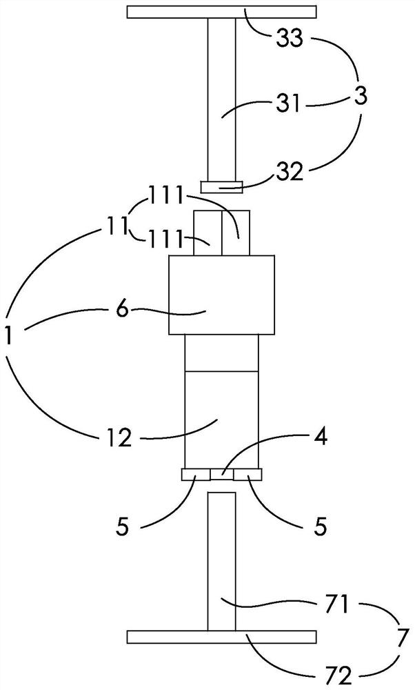
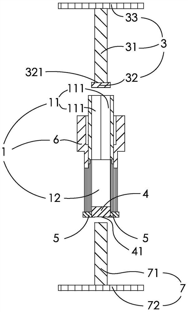
[0037] figure 1 , figure 2 , image 3 , Figure 4 , Figure 5 , Figure 6In the shown embodiment, a kind of powder compacting mold comprises mold cylinder 1, and mold cylinder 1 is made up of upper mold 11, lower mold 12 and peripheral cover 6, and the internal diameter of upper mold 11 and lower mold 12 is equal, and upper mold 11 and The end faces of the lower die 12 are abutted against each other; the upper die 11 is made up of two or more upper die halves 111 that can be separated radially, and a plurality of upper die halves 111 are in the shape of a fan ring, and the size of each upper die halves 111 is uniform. consistent, and each of the upper mold petals 111 is tightly fitted; the peripheral sleeve 6 is sleeved on the radially outer side of the upper mold 11, and the upper mold 11 is provided with an upper pressing rod 3, which can apply force externally. Move in the upper mold 11 and the lower mold 12 under the action, the bottom port of the lower mold 12 is pr...

Embodiment 2

[0046] figure 1 , figure 2 , image 3 , Figure 4 , Figure 5 , Figure 6 In the shown embodiment, a kind of powder pressing mold pressing method comprises the following execution steps

[0047] A1. upper die 11, lower die 12 and peripheral cover 6 described in embodiment 1 are assembled and connected;

[0048] A2. Seal and support the bottom of the lower mold 12;

[0049] A3. Fill the powder to be pressed into the space in the upper mold and the lower mold 12 from above the upper mold until the upper and lower molds are filled with the required rated amount of powder;

[0050] A4. Use the upper pressing rod 3 described in Example 1 to extend from above the upper die 11 into the inner space of the upper die 11 and the lower die 12 containing the powder to be pressed, and the external force is applied to the upper pressing rod 3 and pushes the upper die. Depression bar 3 makes it move on the direction from upper mold 11 to lower mold 12;

[0051] A5. After the upper pr...

Embodiment approach

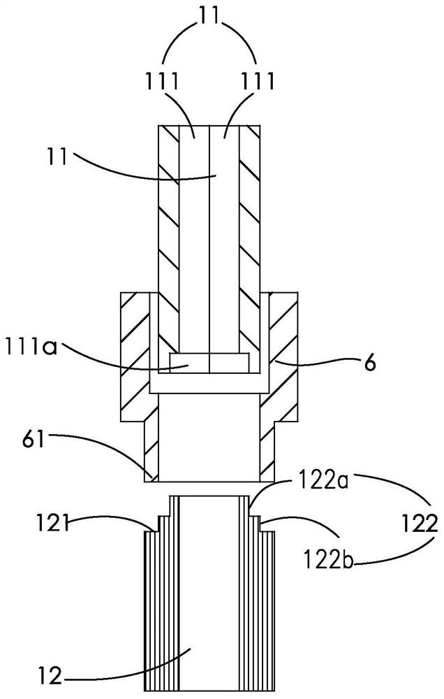
[0056] image 3 It shows an assembly embodiment of an upper mold, a lower mold and a peripheral sleeve. The inner side of the peripheral sleeve 6 is set to have inner diameters of different sizes. The inner diameters with different sizes can be changed by setting a stepped structure to reduce the contact between the inner side of the peripheral sleeve 6 and the outer side of the upper mold 11, and improve the convenience of taking out the upper mold or the green compact after pressing.

[0057] Figure 5 It shows an embodiment of the assembly of the device of the present invention and the molding machine during the pressing process. The molding machine includes a first upper side plate 101 and a first lower side plate 102, and the upper side of the first upper side plate 101 and the upper pressing rod 3. The top plate 33 is fixedly connected, and the positioning cylinder 103 is fixed on the first lower side plate 102. The central axis of the positioning cylinder 103 and the c...


PUM


Abstract

The invention discloses a powder pressing mold and a powder pressing method thereof. The powder pressing mold comprises a mold cylinder, the mold cylinder is composed of an upper mold body, a lower mold and a peripheral sleeve, the inner diameter of the upper mold is equal to that of the lower mold, and the end face of the upper mold abuts against the end face of the lower mold; the upper mold is composed of two or more upper mold petals which can be separated in a radial direction. The peripheral sleeve is connected to the radial outer side of the upper mold in a sleeved mode, an upper pressing rod is arranged above the upper mold and can move in the upper mold and the lower mold under the action of external applied force, a circular truncated cone used for sealing the bottom of the lower mold is arranged in a bottom port of the lower mold, and a lower push rod is arranged below the circular truncated cone. The lower push rod and the circular truncated cone can move in the lower mold under the action of the external applied force. In the mold taking process, the upper mold is taken out firstly, then a pressed blank is taken out, the pressed blank can be taken out from the mold cylinder only by moving the lower mold by a length distance, the situation that the surface smoothness of a pressed part is affected due to long-distance moving and taking-out is avoided, and the requirements for the opening height and the oil cylinder stroke of a molding press during mold taking can be effectively lowered.

Description

technical field [0001] The invention relates to a powder pressing die, in particular to a powder pressing die used for pressing rods or column parts and a powder pressing method thereof. Background technique [0002] Powder compression molding is an industrial technology that uses powder particles as raw materials, fills the powder particles in the cavity of the mold, presses them into the mold by applying pressure, and demoulds to produce various types of products. It is usually used in thermal processing. parts. [0003] In powder compaction operations, such as compacting rods or cylindrical parts, the existing compaction methods usually place the powder directly in a tubular mold for compaction. Since the initial compaction powder is loose, there is a large gap between the powder itself, so that the initial compaction needs to be compacted. The volume occupied by the blank is often several times higher than the volume occupied by the compacted compact after pressing, res...

Claims


Application Information

Patent Timeline
Patent Type & Authority Applications(China)
IPC IPC(8): B30B15/02B30B11/02B30B15/32
CPCB30B15/022B30B11/02B30B15/32
Inventor 刘范李扬帆曾水萍苏芮付新
Owner ZHEJIANG UNIV
Features
  • R&D
  • Intellectual Property
  • Life Sciences
  • Materials
  • Tech Scout
  • Unparalleled Data Quality
  • Higher Quality Content
  • 60% Fewer Hallucinations
Learn More