Step heat storage temperature control system and temperature control method based on phase change energy storage technology

A temperature control system and phase change energy storage technology, applied in heat storage equipment, indirect heat exchangers, heat exchange equipment, etc., can solve the problems of reducing the thermal efficiency of the system, environmental heat pollution, heat waste, etc., to speed up the heat transfer of heat energy speed, improved application performance, improved performance and efficiency

Active Publication Date: 2021-10-29
CHINA PETROLEUM & CHEM CORP +2
View PDF8 Cites 2 Cited by
  • Summary
  • Abstract
  • Description
  • Claims
  • Application Information

AI Technical Summary

Problems solved by technology

[0003]In industrial production, a large amount of waste heat is usually generated, which is generally discharged directly into the atmosphere, and a large amount of heat will be directly dissipated in the air, which not only It will seriously reduce the thermal efficiency of the system, and will cause thermal pollution to the environment; solar energy is a green new energy, which has the advantages of renewability, universality and huge energy, but its disadvantages are discontinuity and volatility
Especially in the petroleum industry, due to the high temperature of wellhead crude oil, flash evaporation usually occurs, which not only leads to the complete loss of part of the crude oil, but also wastes most of the heat

Method used


Image

  • Step heat storage temperature control system and temperature control method based on phase change energy storage technology

Examples


Embodiment 1

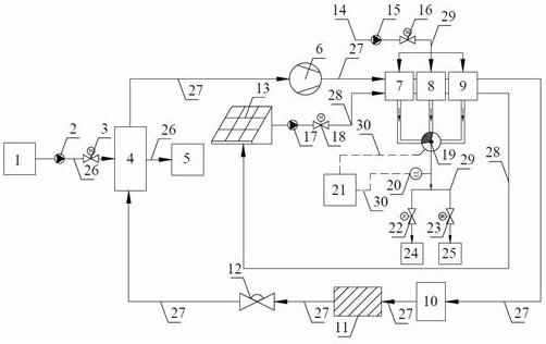
[0031] see figure 1 : A cascaded heat storage temperature control system based on phase change energy storage technology, including a high-temperature heat source 1, the high-temperature heat source 1 flows out through an evaporator 4 through a waste heat pipe 26, and the inlet and outlet of the evaporator 4 are connected through a heat exchange circulation pipe 27, The heat exchange circulation pipe 27 is sequentially connected with the compressor 6, the cascade heat storage device and the liquid storage tank 10;

[0032] It also includes a solar heat collector 13, the inlet and outlet of the solar heat collector 13 are connected through a heat collection circulation pipe 28, and the heat collection circulation pipe 28 is connected with a cascade heat storage device;

[0033] It also includes a normal temperature water source 14, and the normal temperature water source 14 flows out through the heating circulation pipe 29 through the cascade heat storage device and the equipme...

Embodiment 2

[0050] Heat storage process 1 and heat storage process 2 can be carried out simultaneously. Specifically:

[0051] Turn off booster pump 2 15, electric valve 2 16, circulating water pump 17, electric valve 3 18, electric valve 4 22, electric valve 5 23, turn on booster pump 1 2, electric valve 1 3, and turn on circulating water pump 17 and electric valve Three 18,

[0052] The high-temperature heat source 1 and the refrigerant exchange heat in the evaporator 4, the heat released by the high-temperature heat source 1 becomes low-temperature waste heat 5, and the gas-liquid two-phase refrigerant absorbs heat in the evaporator and becomes a low-temperature and low-pressure gas, which enters the compressor 6 The temperature rises and the pressure becomes a high-temperature and high-pressure gas. The high-temperature and high-pressure refrigerant gas enters the cascade heat storage device for condensation and heat release. At the same time, the high-temperature and high-pressure w...

Embodiment 3

[0054] A cascaded heat storage and temperature control system based on phase change energy storage technology mentioned in the present invention differs from Embodiment 1 in that:

[0055] The cascade heat storage device is divided into four heat storage bodies. In the four heat storage bodies, phase change materials with a phase change temperature of 90°C are used, phase change materials with a phase change temperature of 70°C, and a phase change temperature of 50°C are used. The phase change material, the phase change material with a phase change temperature of 30°C.

[0056] Compared with Example 1, this cascade heat storage device adds a heat storage body, which adopts the technology of placing phase change materials with different phase change temperatures in series, which helps to ensure that the temperature difference between the phase change material and the heat exchange fluid is more uniform , improve heat transfer efficiency.

[0057] A cascade heat storage and tem...


PUM


Abstract

The invention provides a step heat storage temperature control system and temperature control method based on a phase change energy storage technology, and belongs to the technical field of phase change heat storage. According to the technical scheme, the step heat storage temperature control system comprises a high-temperature heat source, a solar heat collector, a normal-temperature water source and a temperature control system. The high-temperature heat source flows out of an evaporator through a waste heat pipe, an inlet and an outlet of the evaporator are connected through a heat exchange circulating pipe, and the heat exchange circulating pipe is sequentially connected with a compressor, a step heat storage device and a liquid storage tank; an inlet and an outlet of the solar heat collector are connected through a heat collection circulating pipe, and the heat collection circulating pipe is connected with the step heat storage device. The normal-temperature water source flows out through the step heat storage device and to-be-heated equipment through a heat supply circulating pipe; the temperature control system comprises a controller, a temperature control ball valve and a temperature sensor, wherein the temperature control ball valve and the temperature sensor are arranged on the heat supply circulating pipe. The step heat storage temperature control system and temperature control method based on the phase change energy storage technology has the beneficial effects that through the heat exchange design of different temperature gradients, the storage rate of heat energy is increased, the performance and efficiency of a phase change energy storage device are greatly improved, the heat exchange speed of the heat energy is increased, and the application performance of the phase change energy storage device is improved.

Description

technical field [0001] The invention relates to the field of phase change heat storage technology, in particular to a cascaded heat storage temperature control system and temperature control method based on phase change energy storage technology. Background technique [0002] The basis of phase change heat storage technology is phase change materials, which occur under isothermal or near-isothermal conditions during phase change. Therefore, during the process of energy storage and energy discharge, the temperature and heat flow are basically constant, and accompanied by Lots of heat absorbed / released. Phase change heat storage mainly relies on the latent heat of phase change materials, which has the characteristics of large latent heat and high heat storage density, which is an order of magnitude larger than sensible heat. Since the oil crisis in the 1970s, thermal energy storage technology has been widely used in industrial energy conservation and new energy fields. The ap...

Claims


Application Information

Patent Timeline
Patent Type & Authority Applications(China)
IPC IPC(8): F28D20/02F28F27/00F25B41/31F25B43/00
CPCF28D20/021F28F27/00F25B43/003Y02E60/14
Inventor 孙东齐光峰张强刘向东宋鑫王强范路季学松郑炜博刘聪
Owner CHINA PETROLEUM & CHEM CORP
Why Eureka
Try Eureka