
Phase-sensitive optical time domain reflection system based on dual-wavelength frequency diversity

A technology of phase-sensitive light and frequency diversity, which is applied in the direction of converting sensor output, using optical devices to transmit sensing components, measuring devices, etc., can solve the problems of wasting computing resources, affecting frequency diversity efficiency, and increasing signal processing time, etc., to achieve enhanced The effect of irrelevance, improving frequency diversity efficiency, and avoiding waste

Active Publication Date: 2021-10-29
TAIYUAN UNIV OF TECH
View PDF3 Cites 0 Cited by
  • Summary
  • Abstract
  • Description
  • Claims
  • Application Information

AI Technical Summary

Problems solved by technology

Compared with the single-frequency detection state, the multi-frequency detection state needs to perform operations such as filtering, aggregation, and phase demodulation on the signals of multiple frequency components, resulting in a multiplied signal processing time.
In addition, since the vibration signal does not always exist, multi-frequency detection when there is no external vibration signal will waste a lot of computing resources and seriously affect the real-time performance of the system response
At the same time, the intensity of multiple frequency components in traditional frequency diversity technology is usually fixed, resulting in a certain correlation between Rayleigh backscattered light of different frequencies, which affects the frequency diversity efficiency.

Method used


Image

  • Phase-sensitive optical time domain reflection system based on dual-wavelength frequency diversity

Examples


Embodiment 1

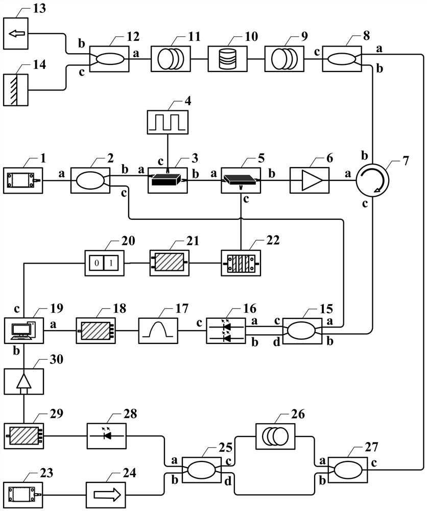
[0024] Such as figure 1 As shown, the embodiment of the present invention provides a dual-wavelength frequency diversity phase-sensitive optical time-domain reflectometry system, including a 1550nm laser 1, a first fiber coupler 2, an acousto-optic modulator 3, a signal generator 4, and a phase modulator 5. Erbium-doped fiber amplifier 6, circulator 7, first wavelength division multiplexer 8, first sensing fiber 9, piezoelectric ceramic 10, second sensing fiber 11, second wavelength division multiplexer 12, the first An optical isolator 13, a Faraday rotating mirror 14, a second fiber coupler 15, a balanced photodetector 16, a bandpass filter 17, a first data acquisition card 18, a computer 19, a random number generator 20, and a digital-to-analog converter 21. Signal power amplifier 22, 1310nm laser 23, second optical isolator 24, third fiber coupler 25, delay fiber 26, fourth fiber coupler 27, photodetector 28, second data acquisition card 29 and threshold comparison device...


PUM


Abstract

The invention belongs to the technical field of distributed optical fiber sensing, and discloses a phase-sensitive optical time domain reflection system based on dual-wavelength frequency diversity. A coherent detection phase-sensitive optical time domain reflection system with a detection light wavelength of 1550nm and an auxiliary interference structure with a detection light wavelength of 1310nm are combined by using a wavelength division multiplexing technology; an external vibration signal is quickly sensed by means of the auxiliary interference structure, so that switching between a single-frequency detection state and a multi-frequency detection state is realized by utilizing computer control, and waste of computing resources caused by multi-frequency detection when no external vibration signal exists is avoided. Besides, in a multi-frequency detection state, a random number generator is utilized to generate a random signal to drive and control a phase modulator, so that random change of the intensity of three frequency components in multi-frequency detection laser is realized, the non-correlation degree among the frequency components in multi-frequency Rayleigh back scattering light is enhanced, and the frequency diversity efficiency is improved. Therefore, the real-time performance of the system can be improved while interference fading suppression is realized.

Description

technical field [0001] The invention belongs to the technical field of distributed optical fiber sensing, in particular to a dual-wavelength frequency diversity phase-sensitive optical time-domain reflection system. Background technique [0002] In recent years, fiber optic vibration sensing technology has attracted the attention of many researchers due to its advantages of corrosion resistance, good insulation, anti-electromagnetic interference, and wide measurement range. As a typical optical fiber vibration sensing system, the phase-sensitive optical time-domain reflectometry system has shown great application potential in the fields of structural health monitoring, perimeter security, and oil and gas pipeline monitoring due to its fast response speed and high sensitivity. [0003] Phase-sensitive optical time-domain reflectometry systems generate probe light from a narrow-linewidth laser that continuously generates Rayleigh backscattered light as it propagates through an...

Claims


Application Information

Patent Timeline
Patent Type & Authority Applications(China)
IPC IPC(8): G01D5/353
CPCG01D5/35361
Inventor 王宇李妍靳宝全高妍张红娟白清刘昕王鹏飞
Owner TAIYUAN UNIV OF TECH
Learn More