Photoelectric liquid level sensor

A liquid level sensor, photoelectric technology, applied in the direction of buoy liquid level indicator, liquid level indicator, instrument, etc., can solve the problems of liquid level sensor switch state switching false alarm, poor protection, reed switch damage, etc., to achieve The production and transportation process is stable and reliable, the detection signal is stable and accurate, and the effect of large difference between high and low voltage

Pending Publication Date: 2021-10-29
常德思高技术有限公司
View PDF0 Cites 1 Cited by
  • Summary
  • Abstract
  • Description
  • Claims
  • Application Information

AI Technical Summary

Problems solved by technology

[0003] 1. Because the reed switch is packaged in glass, it is prone to potential damage during the manufacturing process, and it is impossible to judge whether it is good or bad; and it will also cause potential damage to the reed switch due to poor protection during transportation; The ball liquid level switch is prone to normally on (the reed switch contact is not disconnected), and sometimes it is normal after normally on.
[0004] 2. The reed switch is susceptible to strong magnetic interference, resulting in false detection signals
[0005] 3. After the floating ball with magnet is soaked in the liquid for a long time, it will absorb the magnetic substance in the liquid, and demagnetization and non-magnetization will occur, resulting in an error in the detection signal
[0007] 1. When water mist or water droplets stick to the mirror surface of the tapered end, the liquid level sensor mistakenly thinks that it is immersed in the liquid and produces a switch state switch, resulting in false alarms
[0008] 2. It can only detect the presence or absence of liquid at a fixed point

Method used


Image

  • Photoelectric liquid level sensor
  • Photoelectric liquid level sensor
  • Photoelectric liquid level sensor

Examples


Embodiment Construction

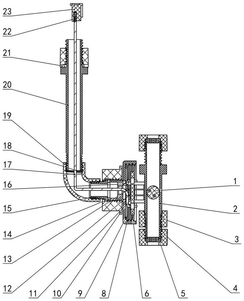
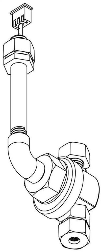
[0044] The present invention provides a photoelectric liquid level sensor. In order to make the purpose, technical solution and effect of the present invention clearer and clearer, the present invention will be further described in detail below with reference to the accompanying drawings.

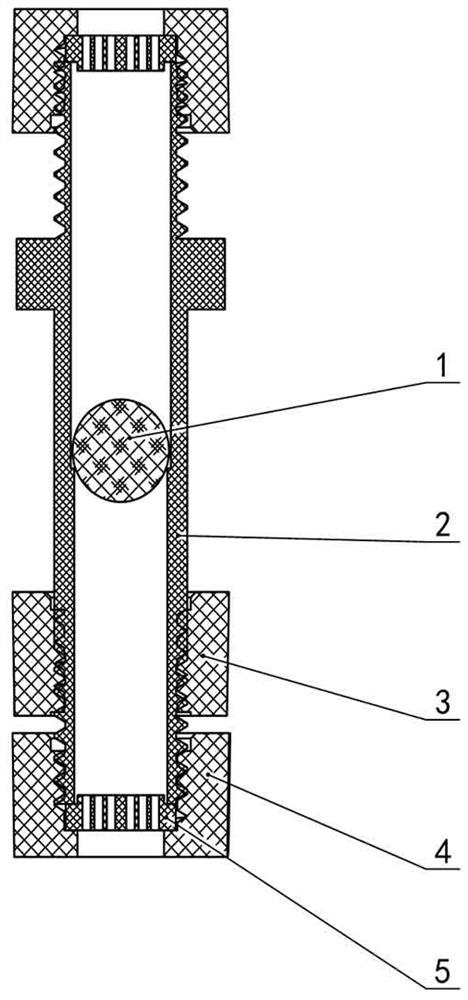
[0045] Such as Figure 1-27 As shown, the present invention includes a float assembly, a photoelectric control assembly, and an installation assembly. The float assembly includes a float 1, a float guide rod 2, a nut A3, a nut B4 and a filter screen 5; the photoelectric control assembly is fixed on On the float guide rod 2 in the float assembly, the photoelectric control assembly includes a transparent casing 7, a PCB board 6, a light pipe bracket 11, an infrared emitting tube 12, an infrared receiving tube 13, an O-shaped sealing ring 9, and a base 8 , nut C10, wire I16, wire II17, wire III18, flat washer ①14, connector 15; the installation assembly is connected to the connector 15, and th...


PUM


Abstract

The invention belongs to a photoelectric liquid level sensor. The photoelectric liquid level sensor comprises a floating ball assembly, a photoelectric control assembly and a mounting assembly, wherein the floating ball assembly comprises a floating ball, a floating ball guide rod, a nut A, a nut B and a filter screen; the photoelectric control assembly comprises a transparent shell, a PCB, a light tube support, an infrared transmitting tube, an infrared receiving tube, an O-shaped sealing ring, a base, a nut C, an electric wire I, an electric wire II, an electric wire III, a flat washer 1 and a connector. The mounting assembly comprises a connecting elbow, a guide rod, a flat washer 2, a nut A, a terminal and a connector, the photoelectric control group is fixed on the floating ball guide rod, and the mounting assembly is connected to the connector. The floating ball is driven to move up and down in the inner cavity of the floating ball guide rod by utilizing the buoyancy of liquid and the gravity of the floating ball, and light rays emitted by the infrared transmitting tube are shielded or avoided through the floating ball, so that the infrared receiving tube generates corresponding low voltage or high voltage to realize liquid level detection; the floating ball is used for directly shielding and avoiding light, generated high and low voltages are large in difference, and detection signals are stable and accurate.

Description

technical field [0001] The invention belongs to a liquid level sensor, in particular to a photoelectric liquid level sensor used in liquid level detection. Background technique [0002] The mechanical float level sensor uses physical magnetic force to operate. When the measured medium floats the float, the float drives the magnet to sense the internal dry reed switch to output the action signal. The float floats up and down with the rise and fall of the liquid water level, and then collects the signal detection The height of the equipment liquid level. Such liquid level sensors have the following problems. [0003] 1. Because the reed switch is packaged in glass, it is prone to potential damage during the manufacturing process, and it is impossible to judge whether it is good or bad; and it will also cause potential damage to the reed switch due to poor protection during transportation; The ball liquid level switch is prone to the bad phenomenon that it is normally on (the...

Claims


Application Information

Patent Timeline
Patent Type & Authority Applications(China)
IPC IPC(8): G01F23/64G01F23/292
CPCG01F23/64G01F23/292
Inventor 刘显生郭惠均
Owner 常德思高技术有限公司
Why Eureka
Try Eureka