
Laser coherent array distributed phase control system and control method

A phase control, distributed technology, applied in the direction of measurement optics, optical radiation measurement, measurement devices, etc., can solve the problems of reducing the effect of coherent combination, increasing the weight and volume of the system, reducing the compactness of the system, etc.

Active Publication Date: 2021-10-29
NAT UNIV OF DEFENSE TECH
View PDF5 Cites 3 Cited by
  • Summary
  • Abstract
  • Description
  • Claims
  • Application Information

AI Technical Summary

Problems solved by technology

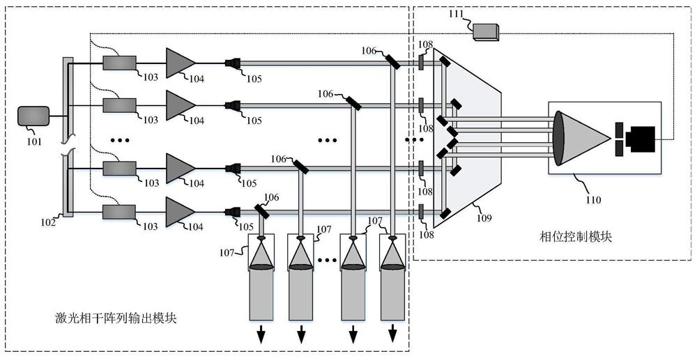
[0004] Since the energy of the central main lobe of the array beam far-field coherent synthesis is used as the evaluation function, such as Figure 1 shows that the phase control algorithm iteration time is approximately proportional to the power of one-half of the number of arrays, and as the number of arrays The increase of the algorithm iteration time will severely limit the phase control rate, reduce the phase control bandwidth, and then reduce the coherent combination effect; at the same time, using this kind of spatial optical path structure for phase control requires not only the spatial optical path adjuster 108 to adjust each laser optical distance, it is also necessary to use a laser beam combiner 109 to narrow the beams of the array and focus them on the same pinhole detector. Too many devices increase the weight and volume of the system, which not only reduces the compactness of the system structure, but also increases the Practical pressures such as thermal management in high power applications

Method used


Image

  • Laser coherent array distributed phase control system and control method
  • Laser coherent array distributed phase control system and control method
  • Laser coherent array distributed phase control system and control method

Examples


Embodiment Construction

[0032] In order to make the purpose, technical solution and advantages of the present application clearer, the present application will be further described in detail below in conjunction with the accompanying drawings and embodiments. It should be understood that the specific embodiments described here are only used to explain the present application, and are not intended to limit the present application.

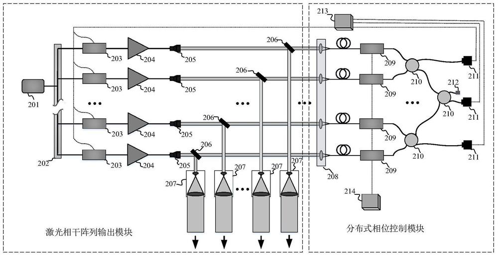
[0033] In one embodiment, such as figure 2 As shown, a laser coherent array distributed phase control system is provided, the system includes: a laser coherent array output module and a distributed phase control module; the distributed phase control module includes: a small lens array 208, a plurality of secondary phase modulation 209, a plurality of fiber couplers 210, a fiber end cap 212, a plurality of photodetectors 211, a primary phase control system 213, and a secondary phase control system 214.

[0034] Preferably, the laser coherent array output module includes: a ...


PUM


Abstract

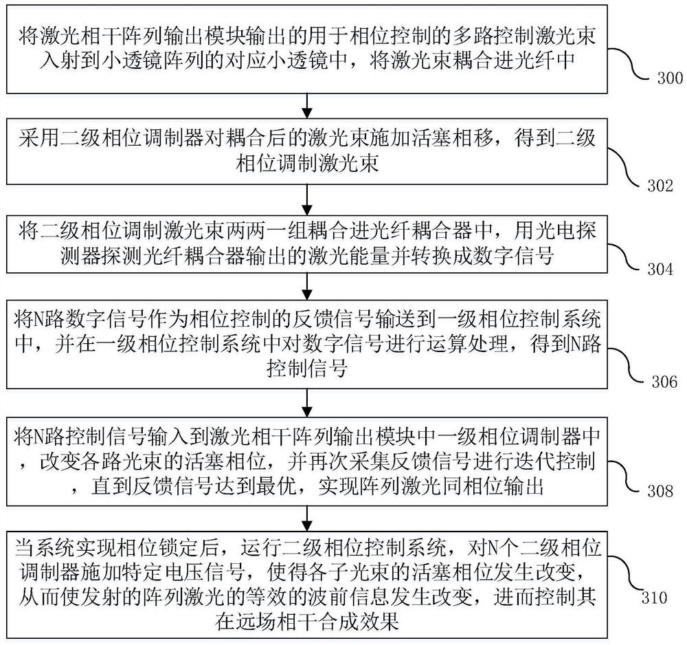
The invention relates to a laser coherent array distributed phase control system and control method. The system comprises a laser coherent array output module and a distributed phase control module, wherein the distributed phase control module comprises a lenslet array, a plurality of secondary phase modulators, a plurality of optical fiber couplers, an optical fiber end cap, a plurality of photoelectric detectors, a primary phase control system and a secondary phase control system; a two-stage phase controller can effectively control wavefront information of array laser, and real-time control over the coherent combination effect of the array laser is achieved; and the optical fiber couplers perform pairwise coupling detection on the phase information of the array light beams without performing unified detection on the phase information of the whole array light beams, so that the phase control bandwidth of the system is improved. The laser coherent array distributed phase control system has the all-fiber feature, the pressure in the aspect of thermal management is reduced, and the compactness and operability of the system structure are improved.

Description

technical field [0001] The present application relates to the field of optical coherent combining technology, in particular to a laser coherent array distributed phase control system and control method. Background technique [0002] The fiber laser coherent array based on the master oscillator power amplification (English name is Master Oscillator Power Amplifier, referred to as MOPA) can realize synthetic aperture emission, increase the system emission aperture, and reduce the laser transmission divergence angle (see patent: CA2278071A1, CN103513428A , CN106451055B, CN103346470B, CN110729628B), are widely used in active imaging and detection, directed energy and laser communication and other fields. [0003] figure 1 It is a structural schematic diagram of a coherent array phase control system in the prior art. The system includes a laser coherent array output module and a phase control module, wherein the laser array output module mainly includes a laser seed source 101,...

Claims


Application Information

Patent Timeline
Patent Type & Authority Applications(China)
IPC IPC(8): G01J9/00
CPCG01J9/00
Inventor 粟荣涛龙金虎靳凯凯侯天悦常琦马阎星马鹏飞周朴司磊许晓军陈金宝
Owner NAT UNIV OF DEFENSE TECH
Learn More