Polishing device for precision casting and positioning and clamping mechanism of polishing device

A technology of precision casting and clamping mechanism, which is applied to grinding drive device, grinding/polishing safety device, grinding frame, etc. Good grinding effect, high precision, avoid random scattering effect

Pending Publication Date: 2021-11-02
ANHUI SOLID FOUNDRY CO LTD
View PDF14 Cites 0 Cited by
  • Summary
  • Abstract
  • Description
  • Claims
  • Application Information

AI Technical Summary

Problems solved by technology

[0003] Precision castings need to be polished after casting to remove the burrs on the outer wall. The existing grinding device will shake during the grinding process, resulting in a decrease in precision castings, and the met

Method used


Image

  • Polishing device for precision casting and positioning and clamping mechanism of polishing device
  • Polishing device for precision casting and positioning and clamping mechanism of polishing device
  • Polishing device for precision casting and positioning and clamping mechanism of polishing device

Examples


Embodiment 1

[0047] see Figure 1-4 , the present invention provides a technical solution: a positioning and clamping mechanism, which is applied to a precision casting grinding device, comprising:

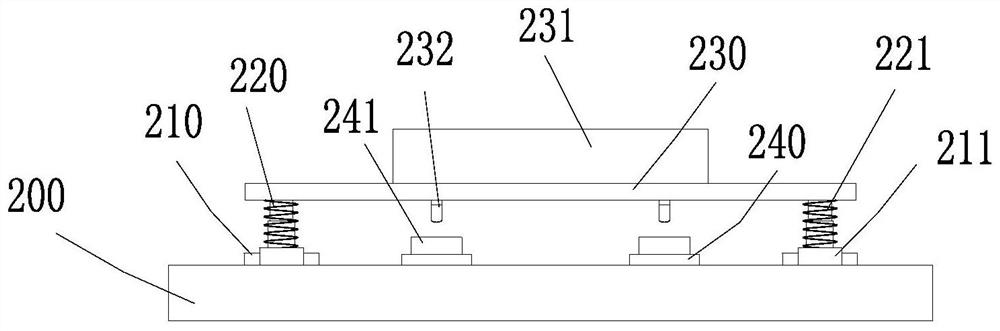
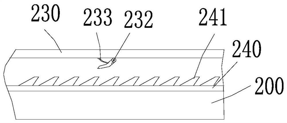
[0048] The workbench 200, the upper end of the workbench 200 is provided with two sets of first slide rails 210 at intervals, each set of the first slide rails 210 is slidably connected with two sets of moving blocks 211, and the upper end of the moving blocks 211 is provided with a telescopic column 220, and the telescopic column 220 is A spring 221 is wound around, a carrier plate 230 is connected to the upper end of the telescopic column 220, and a frame plate 231 is arranged on the upper end of the carrier plate 230. There are rubber sheets;

[0049] The fixing frame 250, the fixing frame 250 is arranged on the upper end of the workbench 200, and is located on the rear side of the two sets of bearing plates 230, a movable plate 251 is movably arranged in the middle of the fixing frame 250...

Embodiment 2

[0055] see Figure 1-4 , the present invention provides a technical solution: a positioning and clamping mechanism, which is applied to a precision casting grinding device, comprising:

[0056] The workbench 200, the upper end of the workbench 200 is provided with two sets of first slide rails 210 at intervals, each set of the first slide rails 210 is slidably connected with two sets of moving blocks 211, and the upper end of the moving blocks 211 is provided with a telescopic column 220, and the telescopic column 220 is A spring 221 is wound around, a carrier plate 230 is connected to the upper end of the telescopic column 220, and a frame plate 231 is arranged on the upper end of the carrier plate 230. There are rubber sheets;

[0057] The fixing frame 250, the fixing frame 250 is arranged on the upper end of the workbench 200, and is located on the rear side of the two sets of bearing plates 230, a movable plate 251 is movably arranged in the middle of the fixing frame 250...

Embodiment 3

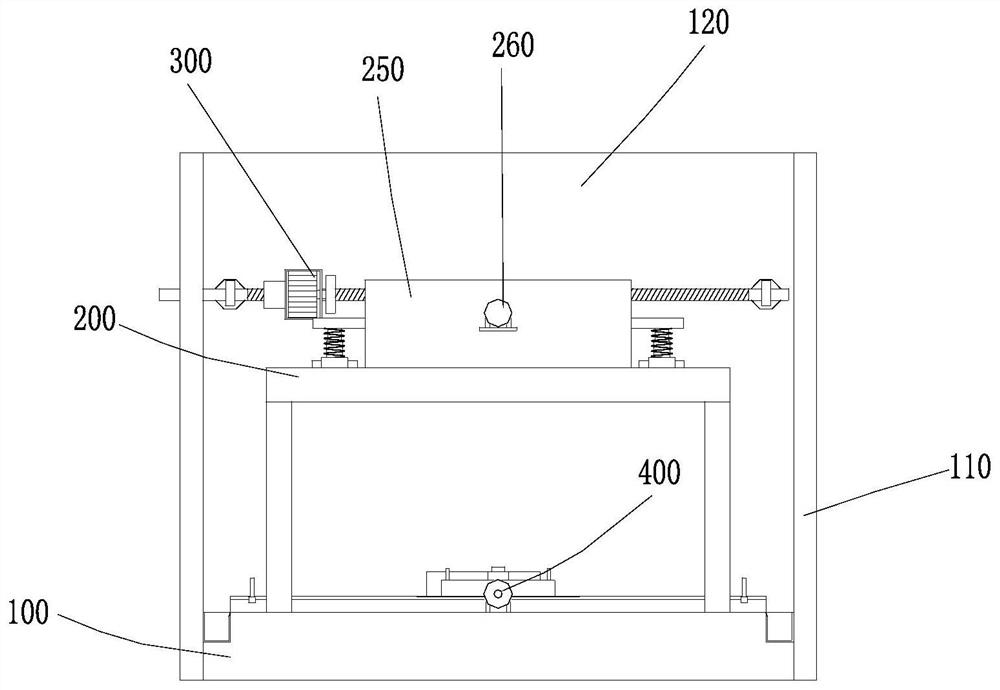
[0064] see Figure 1-10 , the present invention also provides the following technical solutions: a grinding device for precision castings, comprising:

[0065] The base 100, the front side of the base 100 is provided with a back plate 120, the two ends of the back plate 120 are connected with side plates 110, the side walls of the base 100 of the side plate 110 extend backward, and the base 100 is connected with the back plate 120 and the side plate 110. The material chute 130; the collection chute 130 is provided with a collection box 131, the collection box 131 is inclined with a material guide plate on the side close to the scraper mechanism 400, and the back plate 120 and the side plate 110 are respectively provided with through holes for Pick and place the collection box 131 in the collection tank 130;

[0066] A positioning and clamping mechanism in Embodiment 1 or Embodiment 2, which is arranged in the middle of the upper end of the base 100;

[0067] The grinding mec...


PUM


Abstract

The invention discloses a positioning and clamping mechanism. The positioning and clamping mechanism comprises a workbench, a fixing frame, first lining rods and second lining rods; two sets of first sliding rails are arranged at the upper end of the workbench at intervals; each set of first sliding rails is slidably connected to two sets of movable blocks, telescopic columns are arranged at the upper ends of the movable blocks, and the upper ends of the telescopic columns are connected to a bearing plate; the fixing frame is arranged at the upper end of the workbench, a movable plate is movably arranged in the middle of the fixing frame, and racks are arranged on the two sides of the movable plate; the two sets of first lining rods are symmetrically arranged on the front side of the fixing frame with respect to the central axis of the movable plate as the symmetry axis; the two sets of second lining rods are symmetrically arranged on the front side of the fixing frame with respect to the central axis of the movable plate as the symmetry axis and are positioned on the outer sides of the first lining rods; and the movable plate moves forwards along the fixing frame, a rack is meshed with a transmission gear and the transmission gear is meshed with a gear ring, the two sets of clamping arms are driven to rotate at the positions close to each other, the two sides of the precision casting abut against each other, and the movable plate abuts against the rear side of the precision casting. Meanwhile, a polishing device for the precision casting is also provided.

Description

technical field [0001] The invention relates to the technical field of precision casting production, in particular to a grinding device for precision castings and a positioning and clamping mechanism thereof. Background technique [0002] Precision casting refers to the general term for the process of obtaining precise size castings. It is a metal forming object obtained by various casting methods. Compared with the traditional sand casting process, the size of the casting obtained by precision casting is more accurate and the surface finish is better. It mainly includes : Investment casting, ceramic casting, metal casting, pressure casting, lost foam casting. [0003] Precision castings need to be ground and polished after casting to remove the burrs on the outer wall. The existing grinding device will shake during the grinding process, which will reduce the precision of precision castings, and the metal particles generated by grinding are difficult to collect. For this re...

Claims


Application Information

Patent Timeline
IPC IPC(8): B24B9/04B24B41/02B24B41/06B24B55/12B24B47/00B24B47/12B24B47/22B24B41/00
CPCB24B9/04B24B41/02B24B41/06B24B55/12B24B47/00B24B47/12B24B47/22B24B41/007Y02P70/10
Inventor 刘锐汪李劼刘彬彬常勤祥
Owner ANHUI SOLID FOUNDRY CO LTD
Why Eureka
Try Eureka