Sugarcane head and tail removing equipment for food processing

A food processing and sugarcane technology, which is applied in the field of sugarcane head and tail removal equipment for food processing, can solve the problems of sugarcane head and tail removal, time-consuming and labor-intensive work, and low work efficiency, so as to achieve high safety, improve work efficiency, and avoid accidental injuries.

Pending Publication Date: 2021-11-02
陈塘新
View PDF6 Cites 0 Cited by
  • Summary
  • Abstract
  • Description
  • Claims
  • Application Information

AI Technical Summary

Problems solved by technology

[0004] In order to overcome the time-consuming and labor-intensive shortcomings of manually removing the head and tail of sugarcane and the disadvantages of low work efficiency, the technical problem of the present invention is to provide a machine that can automatically load, transport, cut and unload sugarcane and collect materials with high working efficiency. High sugarcane head and tail removal equipment for food processing

Method used


Image

  • Sugarcane head and tail removing equipment for food processing
  • Sugarcane head and tail removing equipment for food processing
  • Sugarcane head and tail removing equipment for food processing

Examples


Embodiment 1

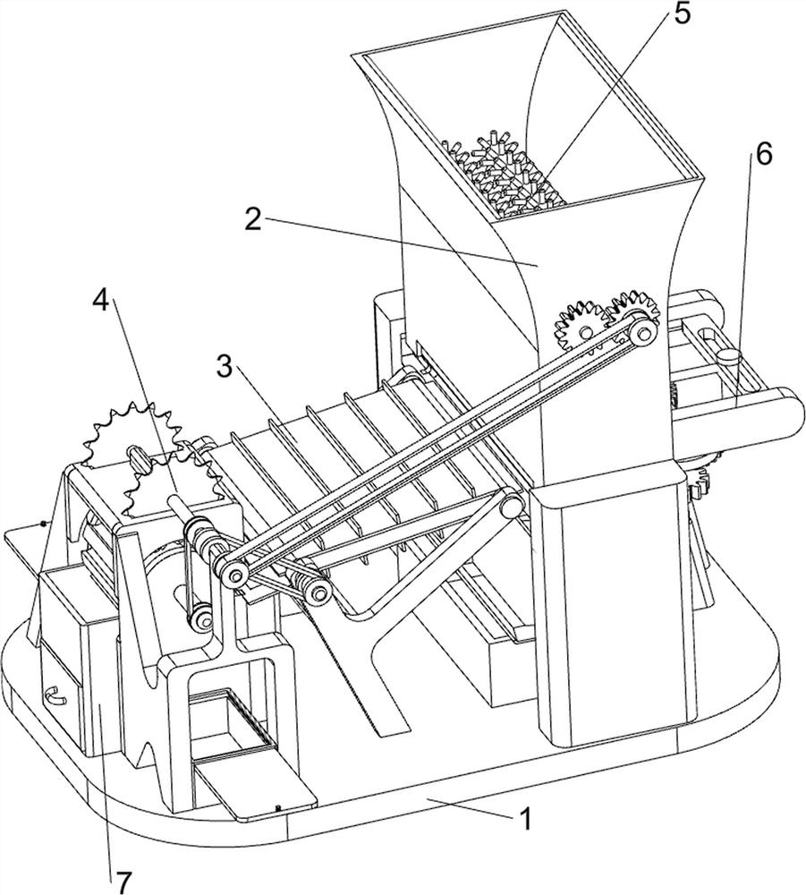
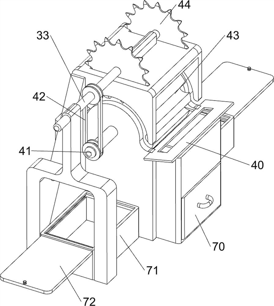
[0065] A kind of equipment for removing sugarcane heads and tails for food processing, such as figure 1 , figure 2 , image 3 with Figure 4 As shown, it includes a bottom plate 1, a feeding mechanism 2, a transmission mechanism 3 and a cutting mechanism 4. The top right side of the bottom plate 1 is provided with a feeding mechanism 2, the top middle side of the bottom plate 1 is provided with a transmission mechanism 3, and the top left side of the bottom plate 1 is provided with a A cutting mechanism 4 is arranged, and the cutting mechanism 4 includes a blanking ramp 40, a fifth drive shaft 41, a third belt 42, a material distribution drum 43 and a saw blade 44, and the left side of the upper part of the bottom plate 1 is provided with a blanking ramp 40, the bottom plate 1. The upper part is left rotating and has a fifth transmission shaft 41. The fifth transmission shaft 41 is provided with a distribution roller 43. A third belt 42 is provided between the fifth transmi...

Embodiment 2

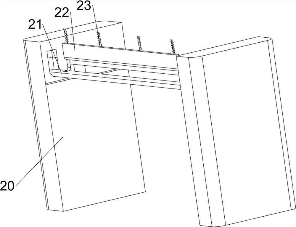
[0070] On the basis of Example 1, such as Figure 4 , Figure 5 and Image 6 As shown, a cleaning mechanism 5 is also included. The cleaning mechanism 5 includes a sixth transmission shaft 50, a first spur gear 51 and a brush roller 52. Both the transmission shaft 50 and the front side of the first transmission shaft 31 are provided with a first spur gear 51 , the first spur gears 51 mesh with each other, and the sixth transmission shaft 50 and the first transmission shaft 31 are both provided with a brush roller 52 .

[0071] When the first transmission shaft 31 rotates, it drives the first straight gear 51 and the sixth transmission shaft 50 to rotate, thereby driving the brush cylinder 52 to rotate, so that the brush cylinder 52 scrubs the sugarcane in the support seat 20, when the first transmission When the shaft 31 stops rotating, the above-mentioned rotations all stop.

[0072] Also include push mechanism 6, push mechanism 6 includes the seventh transmission shaft 60...


PUM


Abstract

The invention relates to removing equipment, in particular to sugarcane head and tail removing equipment for food processing. The technical problem of the invention is to provide the sugarcane head and tail removing equipment for food processing, which can automatically perform feeding, conveying, cutting, discharging and collecting on sugarcanes and is high in working efficiency. The sugarcane head and tail removing equipment for food processing provided by the invention comprises a bottom plate, a feeding mechanism, a conveying mechanism and a cutting mechanism, wherein the feeding mechanism is arranged on one side of the top of the bottom plate; the conveying mechanism is arranged on the middle side of the top of the bottom plate; and the cutting mechanism is arranged on one side of the top of the bottom plate. Through cooperation of the feeding mechanism, the conveying mechanism and the cutting mechanism, sugarcanes can be automatically fed, conveyed and cut, the working efficiency of people is improved, time and labor are saved, people can be prevented from being accidentally injured, and safety is high.

Description

technical field [0001] The invention relates to a cutting device, in particular to a sugarcane head and tail cutting device for food processing. Background technique [0002] Sugarcane is the raw material for making sucrose. Sugarcane is suitable for planting in places with fertile soil, abundant sunshine and large temperature difference between winter and summer. Therefore, sugarcane is widely planted in southern tropical regions such as Taiwan, Fujian, Guangdong, Hainan, Guangxi, Sichuan and Yunnan. [0003] Sugarcane can also be eaten directly. Because the length of sugarcane is longer, people will first remove the head and tail of sugarcane before eating sugarcane, and then cut it into sections for consumption. In terms of current technology, sugarcane is usually processed manually To remove the head and tail, at this time, people need to fix the position of the sugarcane by hand, which is time-consuming and laborious, and the work efficiency is not high, and there is a ...

Claims


Application Information

Patent Timeline
IPC IPC(8): B26D1/15B26D3/16B26D7/06B26D7/27A23N12/00
CPCB26D1/15B26D3/16B26D7/0625B26D7/0641B26D7/27A23N12/005B26D2007/0018Y02A40/90
Inventor 陈塘新
Owner 陈塘新
Why Eureka
Try Eureka