Inert gas circulating device of dry quenching system

A technology of inert gas and circulation device, applied in the field of CDQ system, can solve the problems of affecting production and processing efficiency, slow cooling efficiency of inert gas, etc., and achieve the effects of improving the fluidity of water body, improving the effect of circulating cooling, and enhancing the effect of heat exchange.

Pending Publication Date: 2021-11-02
QINGDAO DESHIPU MACHINERY IND
View PDF4 Cites 0 Cited by
  • Summary
  • Abstract
  • Description
  • Claims
  • Application Information

AI Technical Summary

Problems solved by technology

Usually CDQ is the abbreviation of coke dry quenching. In the process of dry quenching, red coke at 1000°C is loaded from the top of the CDQ furnace, and low-temperature inert circulating gas at 130°C is blown into the red coke in the cooling section of the CDQ furnace by a circulating fan. In the layer, the sensible heat of red coke is absorbed, and the cooled coke (less than 200°C) is discharged from the bottom of the CDQ furnace, and the high-temperature inert gas from the annular flue of the CDQ furnace flows through the CDQ boiler for heat exchange, and the boiler produces The steam and the cooled inert gas are reblown into the CDQ furnace by the circulating fan, and the inert gas is recycled in the closed system, but the structure used for cooling the inert gas in the traditional CDQ system is relatively simple, which leads to its inertness. Gas cooling efficiency is slow, which affects the overall production and processing efficiency of the system

Method used


Image

  • Inert gas circulating device of dry quenching system
  • Inert gas circulating device of dry quenching system
  • Inert gas circulating device of dry quenching system

Examples


Embodiment Construction

[0027] The following will clearly and completely describe the technical solutions in the embodiments of the present invention with reference to the accompanying drawings in the embodiments of the present invention. Obviously, the described embodiments are only some, not all, embodiments of the present invention. Based on the embodiments of the present invention, all other embodiments obtained by persons of ordinary skill in the art without making creative efforts belong to the protection scope of the present invention.

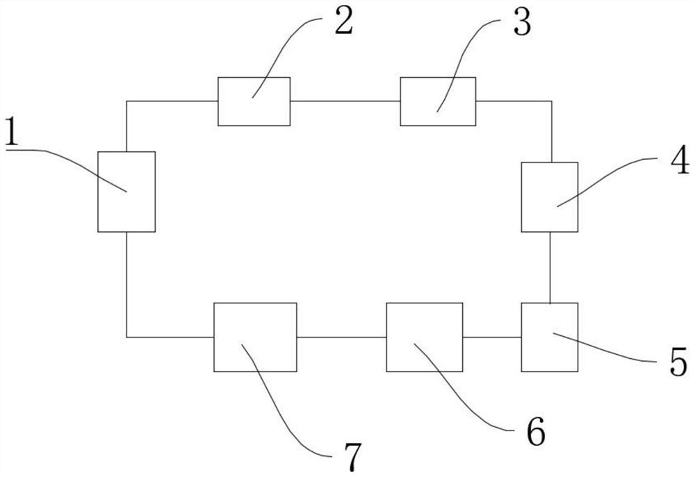
[0028] see Figure 1-8 , the present invention provides a technical solution: an inert gas circulation device for CDQ system, including CDQ furnace 1, primary dust collector 2, CDQ waste heat boiler 3, secondary dust collector 4, primary cooling device 5, fan 6 and secondary cooling device 7, CDQ furnace 1, primary dust collector 2, CDQ waste heat boiler 3, secondary dust collector 4, primary cooling device 5, fan 6, and secondary cooling device 7 are all carr...


PUM


Abstract

The invention discloses an inert gas circulating device of a dry quenching system. The inert gas circulating device comprises a dry quenching furnace, a primary dust remover, a dry quenching waste heat boiler, a secondary dust remover, a primary cooling device, a fan and a secondary cooling device; the dry quenching system inert gas circulating device is composed of the dry quenching furnace, the primary dust remover, the dry quenching waste heat boiler, the secondary dust remover, the primary cooling device, the fan and the secondary cooling device, and the primary cooling device is composed of the heat exchanger body, the outer shell and the heat exchange pipeline, the heat exchanger body and the outer shell are provided with the first mounting groove and the second mounting groove correspondingly, so that the air cavity is formed between the first mounting groove and the second mounting groove, and workers can conveniently and regularly clean the side walls of the first mounting groove and the second mounting groove through detachable mounting between the heat exchanger body and the outer shell; therefore, the heat conduction effect of the device is prevented from being influenced by soot accumulation, and the heat exchange efficiency is further prevented from being influenced.

Description

technical field [0001] The invention relates to the related technical field of coke dry quenching system, in particular to an inert gas circulation device of coke dry quenching system. Background technique [0002] The so-called dry coke quenching is relative to wet coke quenching, and refers to a coke quenching method that uses inert gas to cool red coke. Usually CDQ is the abbreviation of coke dry quenching. In the process of dry quenching, red coke at 1000°C is loaded from the top of the CDQ furnace, and low-temperature inert circulating gas at 130°C is blown into the red coke in the cooling section of the CDQ furnace by a circulating fan. In the layer, the sensible heat of red coke is absorbed, and the cooled coke (less than 200°C) is discharged from the bottom of the CDQ furnace, and the high-temperature inert gas from the annular flue of the CDQ furnace flows through the CDQ boiler for heat exchange, and the boiler produces The steam and the cooled inert gas are reblo...

Claims


Application Information

Patent Timeline
Patent Type & Authority Applications(China)
IPC IPC(8): C10B39/02
CPCC10B39/02Y02P20/129
Inventor 韩永胜
Owner QINGDAO DESHIPU MACHINERY IND
Why Eureka
Try Eureka