Check patentability & draft patents in minutes with Patsnap Eureka AI!

Circuit topology for dynamic wireless power supply multiplexing emission guide rail LCL compensation

A technology for transmitting rails and wireless power supply, applied in circuit devices, high-efficiency power electronic conversion, electrical components, etc., can solve the problems of unsolved hard switching of two-section rails at the same time power supply, multi-length power supply lines, and easy-to-burn devices. The effect of constant current control difficulty, reducing design difficulty and improving robustness

Pending Publication Date: 2021-11-02
HARBIN INST OF TECH
View PDF0 Cites 0 Cited by
  • Summary
  • Abstract
  • Description
  • Claims
  • Application Information

AI Technical Summary

Problems solved by technology

This method has a simple structure and low cost, but requires more power supply lines and longer lengths, and the switch is in a hard switching state, which is easy to burn the device, and it is difficult to open two sections of guide rails at the same time
[0007] (2) The multi-source independent power supply scheme refers to the provision of a transmitting power supply for each section of the power supply rail. This method eliminates the switch, simple structure, and easy switching. However, the number of power supplies is too large and the cost is high.
[0008] (3) The multi-source hybrid power supply scheme is an improvement to the single-source segmented power supply, which reduces the number of segments driven by each power supply rail to reduce the pressure on a single power supply, but it still does not solve the problem of hard switching and simultaneous power supply of two rails question
[0010] In summary, for the transmitter of the dynamic wireless power supply system, the compensation topology with no-load, fast response, small size, low cost, and high efficiency and the switching method with less power supply, soft switching, and multi-rail simultaneous operation need further research.

Method used


Image

  • Circuit topology for dynamic wireless power supply multiplexing emission guide rail LCL compensation
  • Circuit topology for dynamic wireless power supply multiplexing emission guide rail LCL compensation
  • Circuit topology for dynamic wireless power supply multiplexing emission guide rail LCL compensation

Examples


Embodiment Construction

[0042] The technical solutions in the embodiments of the present invention will be described in conjunction with the accompanying drawings, hereby embodiments of the invention are merely, and the described embodiments are merely the embodiments of the present invention, not all of the embodiments; In the present invention, there are all other embodiments obtained without making creative labor premistence, in the art.

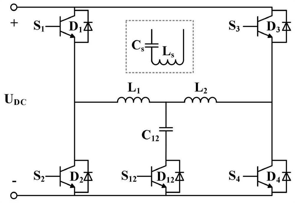
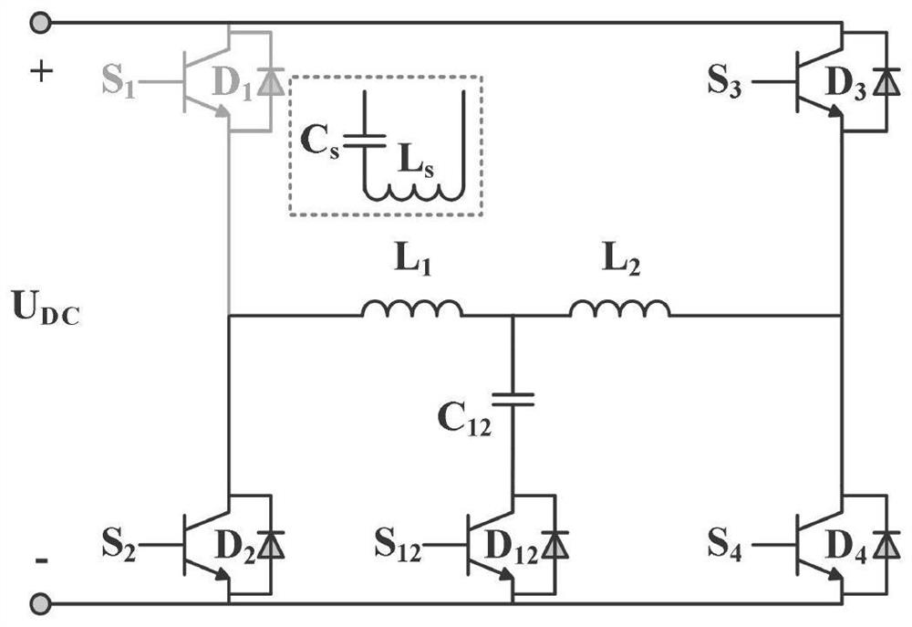
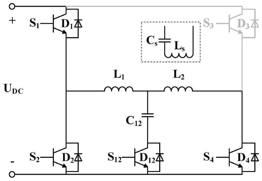
[0043] A circuit topology for dynamic wireless power supply multiplexing launch rail LCL compensation: figure 1 Indicated;

[0044] The circuit topology includes a DC bus voltage U DC , Reverse source switch tube S 1 S 2 S 3 S 4 S 12 , LCL compensation circuit and receiving end;

[0045] The LCL compensation circuit includes self-inductance L of two adjacent launches. 1 And L 2 , Resonant compensation capacitor C 12 ;

[0046] The receiving end includes receiving end self-sensing L s And compensation capacitance C s ;

[0047] Resonant compensation capacitor C 12 On...


PUM


Abstract

The invention provides a circuit topology for dynamic wireless power supply multiplexing transmitting guide rail LCL compensation. The circuit topology comprises a direct current bus voltage UDC, inverter source switch tubes S1, S2, S3, S4 and S12, an LCL compensation circuit and a receiving end. The LCL compensation circuit comprises self-inductors L1 and L2 of two adjacent emission guide rails and a resonance compensation capacitor C12; the receiving end comprises a receiving end self-inductor Ls and a compensation capacitor Cs, the multiplexing transmitting guide rail compensates for the adjacent guide rails, and a compensation inductor does not need to be additionally configured for each section of guide rail; a multiplexing inverter source bridge arm can drive two sections of guide rails by adopting one inverter source; and according to a multiplexing resonant capacitors, only one resonant capacitor need to be configured for the two guide rails. And due to high multiplexing of the system, the use of devices is reduced, the size and cost of the system are reduced, the loss is reduced, and the efficiency of the system is improved.

Description

Technical field [0001] The present invention pertains to wireless dynamic wireless power transmission and power supply, and in particular, to a dynamic wireless power circuit topology rail multiplexed transmission LCL compensation. Background technique [0002] Dynamic real-time wireless power technology can supplement energy in electric cars with the process, it is possible to increase mileage and reduce the ratio of battery power, bringing to overcome the drawbacks of traditional wired charging has important research value. We are now moving in the direction of high-power, long-distance, long mileage of continuous development. Research on wireless power feeding technique of dynamic domestic and international long main rail and around a multi-coil arrangement of the magnetic coupling type deployment mechanism, the structure and properties of its own, the core configuration, the coupling performance characteristics, the lateral offset capability, resonant topology to compensate d...

Claims


Application Information

Patent Timeline
Patent Type & Authority Applications(China)
IPC IPC(8): H02J50/12H02M7/5387
CPCH02J50/12H02M7/5387Y02B70/10
Inventor 高鑫程远杜博超崔淑梅
Owner HARBIN INST OF TECH
Features
  • R&D
  • Intellectual Property
  • Life Sciences
  • Materials
  • Tech Scout
  • Unparalleled Data Quality
  • Higher Quality Content
  • 60% Fewer Hallucinations
Learn More