
Position control system and method for axial centering roller of ring rolling mill

A control system, technology for centering rolls, used in metal rolling and other directions

Active Publication Date: 2021-11-05
CHINA NAT HEAVY MACHINERY RES INSTCO
View PDF6 Cites 1 Cited by
  • Summary
  • Abstract
  • Description
  • Claims
  • Application Information

AI Technical Summary

Problems solved by technology

[0004] In the prior art, there is no method that can conveniently and accurately determine the position control of the axial centering roll in the ring rolling mill rolling process of the workpiece

Method used


Image

  • Position control system and method for axial centering roller of ring rolling mill
  • Position control system and method for axial centering roller of ring rolling mill
  • Position control system and method for axial centering roller of ring rolling mill

Examples


Embodiment 1

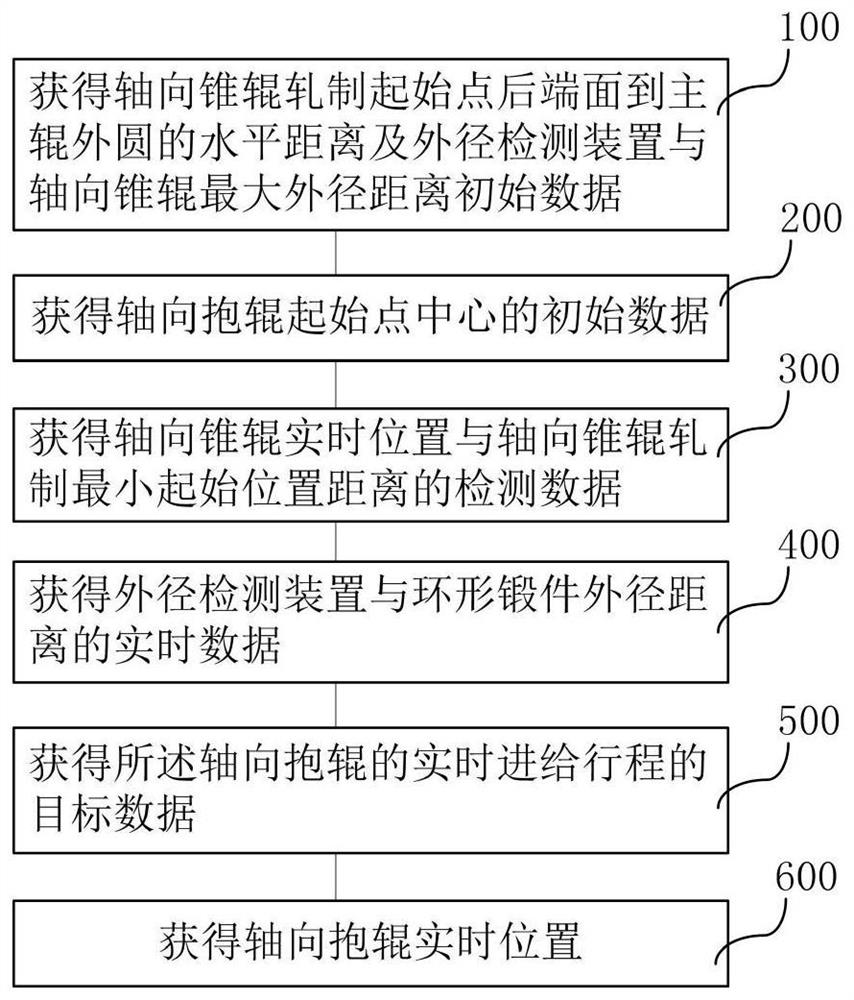
[0048] This embodiment relates to a method for controlling the position of the axial centering roll in the rolling process of a ring rolling mill, see image 3 Shown: This method is used to limit the jumping and swinging phenomenon of the ring forging during the rolling process of the ring rolling mill, reduce the offset force caused by asymmetric rolling and reduce the ellipticity of the ring forging. The specific steps include:

[0049] Step 100, obtaining the initial data B of the horizontal distance from the rear end face of the rolling starting point of the axial tapered roller to the outer circle of the main roller and the distance F between the outer diameter detection device and the maximum outer diameter of the axial tapered roller;

[0050] Step 200, obtaining the initial data of the center of the starting point of the axial centering roller. The initial data of the starting point center of the axial centering roll is the horizontal distance V between the starting po...

Embodiment 2

[0071] The axial centering roller device involved in this embodiment has a displacement sensor, and the axial centering roller device feeds back its feed data through the displacement sensor.

[0072] In the above embodiment, when obtaining the feed of the axial centering roller device, the displacement sensor in the axial centering roller device is used to measure the feed amount of the axial centering roller device, and the displacement sensor finally converts the measured Feed data is fed back to the axial centering roll position control system of the ring rolling mill. The position control system of the axial centering roll of the ring rolling machine finally adjusts the real-time feed stroke of the axial centering roll of the ring rolling machine according to the comparison of the feed amount feedback data and the target data.

Embodiment 3

[0074] The position control of the axial centering roller involved in this embodiment is to control the feeding position data of the centering roller through the hydraulic servo control system according to the feed amount data measured and fed back by the displacement sensor.

[0075] In the above embodiment, the hydraulic servo control system controls the displacement feed of the axial centering roller by comparing the feedback data of the axial centering roller displacement sensor with the target data.


PUM


Abstract

The invention provides a position control system and method for an axial centering roller of a ring rolling mill. The position control system comprises a processing unit and a signal receiving module; the signal receiving module is used for transmitting received data to the processing unit; and the processing unit is used for acquiring data of the signal receiving module and running a computer program. The invention further relates to a control method of the system. In the rolling process of an annular forge piece, the real-time distance between the current position of the axial conical roller and the minimum rolling starting position of the axial conical roller and the real-time distance between the outer diameter detection device and the outer diameter of the annular forge piece are adopted, the real-time stroke of the centering roller can be accurately calculated, and the position of the axial centering roller is controlled through a hydraulic servo control system; and in the rolling process of the annular forge piece, the jumping and swinging phenomena of the annular forge piece are limited, the deviation force caused by asymmetric rolling is reduced, the ovality of the annular forge piece is reduced, a basis is provided for real-time diameter detection and roundness of the annular forge piece, and a basis is provided for stable proceeding of the rolling process.

Description

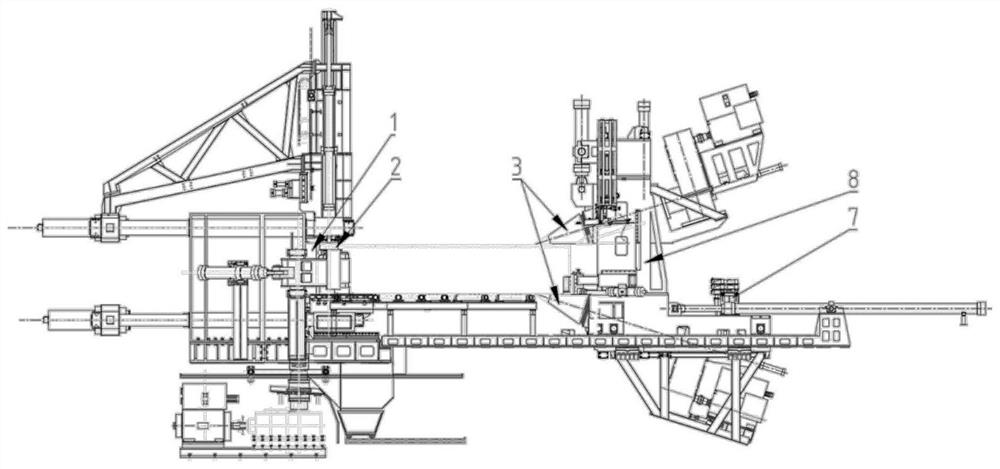
technical field [0001] The invention belongs to the field of metal rolling; in particular, it relates to a position control system and method for an axial centering roll of a ring rolling machine. Background technique [0002] During the rolling process of the ring forging, its local force is applied and the contact area is asymmetrical, which is prone to violent jumping and swinging, and causes the ring forging to generate offset force, resulting in serious deformation of the geometric dimension of the ring forging during rolling. [0003] In order to control the beating and swinging phenomenon during the rolling process of ring forgings, reduce the offset force caused by asymmetrical rolling and return the ring forgings to circle, a centering roller system is added. The centering roller is in contact with the ring forging and rotates drivenly under the action of friction. As the diameter of the ring forging increases, the centering roller moves backwards under the action ...

Claims


Application Information

Patent Timeline
Patent Type & Authority Applications(China)
IPC IPC(8): B21H1/06
CPCB21H1/06
Inventor 曹文胜付永涛柴星张宗元王斌
Owner CHINA NAT HEAVY MACHINERY RES INSTCO
Learn More