Supercharge Your Innovation With Domain-Expert AI Agents!

Steel-plastic composite pipe end flange welding system

A steel-plastic composite pipe and flange welding technology, applied in welding equipment, welding equipment, auxiliary welding equipment, etc., can solve problems such as welding obstruction, difficulty in dismantling tooling, and difficulty in ensuring welding quality, and achieve the effect of avoiding deviation

Pending Publication Date: 2021-11-05
GUANGZHOU BIYUAN PIPE IND CO LTD
View PDF0 Cites 0 Cited by
  • Summary
  • Abstract
  • Description
  • Claims
  • Application Information

AI Technical Summary

Problems solved by technology

[0002] The pipe end connection flange is an existing technology, but at present, the steel pipe and the flange are usually fixed by clamps, and then welded. Both the steel pipe and the flange are fixed, but the clamps also hinder the welding. Therefore, manual welding is usually used for welding, and the welding quality is difficult to guarantee
Another way is to fix the flange on the end of the steel pipe through tooling and then weld it by a robot. The welding accuracy is high, but the subsequent removal of the tooling is very difficult and time-consuming

Method used


Image

  • Steel-plastic composite pipe end flange welding system
  • Steel-plastic composite pipe end flange welding system
  • Steel-plastic composite pipe end flange welding system

Examples


Embodiment 1

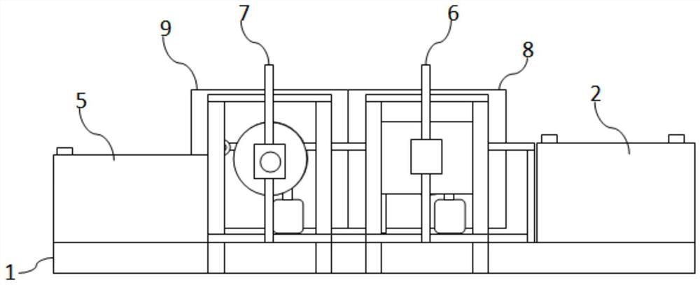
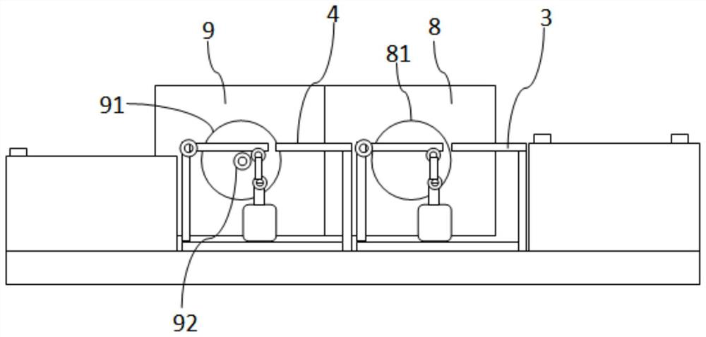
[0032] Such as Figure 1-8 As shown, a steel-plastic composite pipe end flange welding system includes a bottom frame 1, a feeding frame 2, a first fixed frame 3, a second fixed frame 4 and a temporary storage frame 5, and the bottom frame 1 is viewed from the right. To the left, a loading rack 2, a first fixing rack 3, a second fixing rack 4 and a temporary storage rack 5 are installed in sequence;

[0033] The top surface of the loading rack 2 is used for stacking steel pipes to be processed;

[0034] The first fixed frame 3 includes a frame A31, a first joint 32, a first connecting rod 33, a second joint 34, a second connecting rod 35, a third joint 36 and an air cylinder A37, wherein the first joint 32, the first connecting rod There are two sets of rod 33, second joint 34, second connecting rod 35, third joint 36 and cylinder A37, which are respectively arranged on the front and rear end surfaces of frame A31. There is a gap on the upper left side of frame A31, and the f...

Embodiment 2

[0045] The housing 93 of the welding auxiliary mechanism 9 is located above the turntable 91 and is provided with an upper cover 15. The front end of the upper cover 15 is vertically provided with several vertical bars 16. The lower end of the vertical bar 16 is connected with a mounting block 17, and the front end of the mounting block 17 is installed with The baffle C18, when in use, the position of the baffle C18 is adjusted to the top of the steel pipe to be processed, at least can not interfere with the rolling and transfer of the steel pipe. The function of the baffle plate C18 is to prevent the spattering range of sparks generated during welding from being too large, so as to improve production safety. Other structures of this embodiment are the same as those of Embodiment 1.

[0046] The above-described embodiments can be combined with each other.

[0047] Using method of the present invention (taking embodiment 1 as example):

[0048] 1) Use tools such as a crane or...


PUM


Abstract

The invention relates to the technical field of steel pipe machining, and particularly relates to a steel-plastic composite pipe end flange welding system. The steel-plastic composite pipe end flange welding system comprises a bottom frame, a feeding frame, a first fixing frame, a second fixing frame and a temporary storage frame; the feeding frame, the first fixing frame, the second fixing frame and the temporary storage frame are sequentially installed on the bottom frame from right to left; a pipe pushing mechanism is installed on the bottom frame and located behind the first fixing frame and used for pressing a to-be-machined steel pipe and a flange plate, and a worker can conveniently use a manual welding gun for spot welding of a plurality of sites so that the flange plate can be temporarily connected to the end of the to-be-machined steel pipe; a welding auxiliary mechanism is installed on the bottom frame and located behind the second fixing frame and comprises a shell and a rotary disc; and the rotary disc is used for pressing the to-be-machined steel pipe and the flange plate, the rotary disc is used for driving the steel pipe and the flange plate to rotate, a welding robot is used for being aligned with the junction of the flange plate and the end of the steel pipe for fixed-point welding, welding can be completed by rotating the steel pipe by a circle, and therefore formed welding lines are uniform, strength is high, and operation is easy, convenient and fast.

Description

technical field [0001] The invention relates to the technical field of steel pipe processing, in particular to a flange welding system at the end of a steel-plastic composite pipe. Background technique [0002] The pipe end connection flange is an existing technology, but at present, the steel pipe and the flange are usually fixed by a clamp, and then welded, the steel pipe and the flange are fixed, but the clamp also hinders the welding, Therefore, manual welding is usually used for welding, and the welding quality is difficult to guarantee. Another way is to fix the flange on the end of the steel pipe through tooling and then weld it by a robot. The welding accuracy is high, but the subsequent removal of the tooling is very difficult and time-consuming. Contents of the invention [0003] Aiming at the deficiencies of the prior art, the invention provides a device for welding the end of the steel pipe and the flange, which is easy to operate and has high working efficien...

Claims


Application Information

Patent Timeline
IPC IPC(8): B23K37/053B23K37/00B23K31/02
CPCB23K37/053B23K37/0538B23K37/00B23K37/006B23K31/02
Inventor 王志开陶燕春
Owner GUANGZHOU BIYUAN PIPE IND CO LTD
Features
  • R&D
  • Intellectual Property
  • Life Sciences
  • Materials
  • Tech Scout
  • Unparalleled Data Quality
  • Higher Quality Content
  • 60% Fewer Hallucinations
Learn More