Fireproof outer layer isolation system for bridge stay cable

A technology of isolation system and fire protection layer, applied in the direction of bridges, cable-stayed bridges, bridge forms, etc., can solve the problems of poor construction consistency, bridge safety threats, low construction efficiency, etc., to improve sealing and structural stability, good fire prevention. The effect of sealing effect and improving construction efficiency

Active Publication Date: 2021-11-05
JIANGSU CUMT DAZHENG SURFACE ENG TECH
View PDF25 Cites 0 Cited by
  • Summary
  • Abstract
  • Description
  • Claims
  • Application Information

AI Technical Summary

Problems solved by technology

For cable system bridges, the cables are the main load-bearing components of the bridge. Once damaged in a fire, the traffic will be blocked, causing huge economic losses, and at the same time pose a great threat to the safety of the bridge.
At present, some cable system bridges have encountered different degrees of fire during operation, causing certain losses
[0003] In the prior art, great attention has been paid to the setting of the fireproof layer of the outer layer of the cable, but the existing fireproof layer is all on-site construction, its construction efficiency is low, and the construction period is long. Prolonged repair time
Moreover, due to poor construction consistency caused by human construction, structural defects due to human construction cannot be avoided

Method used


Image

  • Fireproof outer layer isolation system for bridge stay cable
  • Fireproof outer layer isolation system for bridge stay cable
  • Fireproof outer layer isolation system for bridge stay cable

Examples


Embodiment Construction

[0041] Next, the technical solutions in the embodiments of the present invention will be described in connection with the drawings of the embodiments of the present invention, and it is understood that the described embodiments are merely the embodiments of the present invention, not all of the embodiments. Based on the embodiments of the present invention, all other embodiments obtained by those of ordinary skill in the art are in the range of the present invention without making creative labor premise.

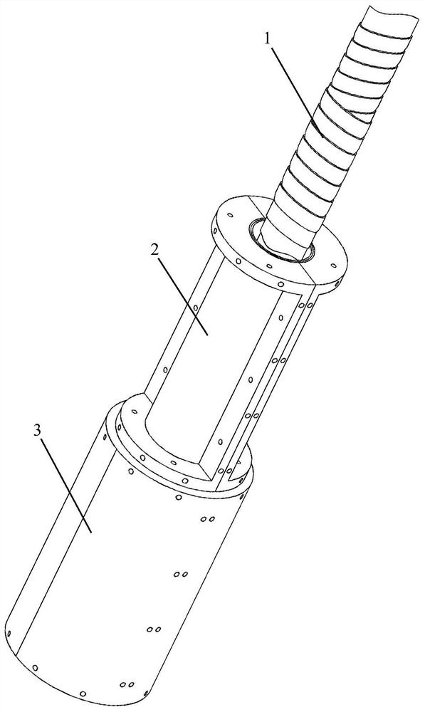
[0042] See figure 1 Attachment Figure 9 , Outer embodiments disclose fire isolation system for a stay cable bridge, comprising a cable, and wrapping the protective sleeve on the outside of the cable HDPE of the present invention; further comprising:

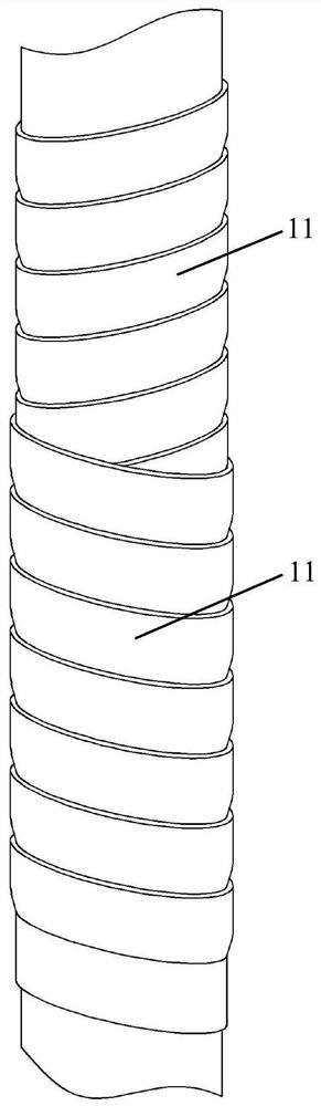
[0043] A fire barrier layer; a fire barrier layer comprises two layers of helically wound outer protective sheath HDPE basalt fiber cloth 11, two opposite winding direction of basalt fiber cloth 11;

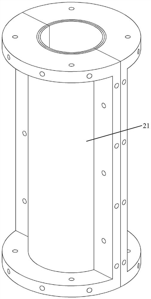
[0044] The holding seal layer ...


PUM


Abstract

The invention discloses a fireproof outer layer isolation system for a bridge stay cable. The fireproof outer layer isolation system comprises a stay cable and an HDPE protective sleeve wrapping the outer side of the stay cable. The fireproof layer comprises two layers of basalt fiber cloth strips which are spirally wound on the outer side of the HDPE protective sleeve, and the winding directions of the two layers of basalt fiber cloth strips are opposite; an inner fastening and sealing layer comprises a plurality of sections of inner sealing sleeves which are arranged on the outer side of the fireproof layer in a sleeving manner; each inner sealing sleeve comprises two inner semicircular pipes, and a plurality of layers of basalt gridding cloth are bonded on the inner walls of the inner semicircular pipes and are bonded and fixed with the basalt fiber cloth strips; an outer protective sealing layer comprises a plurality of sections of outer sealing sleeves arranged on the outer side of the inner fastening and sealing layer in a sleeving manner; the outer sealing sleeve comprises two outer semicircular pipes, and a plurality of layers of basalt gridding cloth are adhered to the inner walls of the outer semicircular pipes; and the outer semicircular pipes are connected to the outer sides of the inner semicircular pipes. A prefabricated assembly mode can be achieved, the construction efficiency is improved, the sealing effect after assembly meets the requirement, and meanwhile, the anti-collision and anti-damage capacity of an isolation system can be improved.

Description

Technical field [0001] The present invention relates to a cable fire prevention and cable - stayed bridge technology, and more particularly, it relates to fire the outer isolation system for a stay cable bridge. Background technique [0002] my country from the 1990s began the construction of large-scale structure of the cable hanging bridges, construction of the run for nearly 30 years, the bridge, the incidence of accidents and disasters runtime also will increase, to society caused immeasurable loss. With the development of economic and social development, an increase in bridge traffic, vehicle transport inflammable and explosive materials on the bridge have continued to increase, resulting in a vehicle fire burning more and more events, fire prevention for bridge gradually attention. For cable system bridge, cable bridge as the main load-bearing components, once damaged in the fire, will cause traffic congestion, causing huge economic losses, at the same time pose a great thr...

Claims


Application Information

Patent Timeline
IPC IPC(8): E01D19/16E01D11/04B32B1/08B32B27/32B32B9/00B32B9/04
CPCE01D19/16E01D11/04B32B1/08B32B27/32B32B27/12B32B5/02B32B5/26B32B2262/10B32B2307/3065B32B2307/558
Inventor 康壮苏倪雅方二宝邵宁张兵
Owner JIANGSU CUMT DAZHENG SURFACE ENG TECH
Why Eureka
Try Eureka