Water chilling unit suitable for hydrogen refueling station and using method of water chilling unit

A chiller and hydrogenation machine technology, applied in the field of hydrogenation stations, can solve the problems that it takes a certain time to reach a usable state, consumes a large amount of electric energy, and the hydrogenation station is unacceptable, so as to shorten the hydrogenation time, save energy, and The effect of compact equipment

Active Publication Date: 2021-11-05
上海氢枫能源技术有限公司
View PDF8 Cites 0 Cited by
  • Summary
  • Abstract
  • Description
  • Claims
  • Application Information

AI Technical Summary

Problems solved by technology

[0002] The chillers equipped in existing hydrogen refueling stations are not specially suitable for hydrogen refueling stations. Usually, separate chillers are required for compression equipment and hydrogen refueling machines. According to the actual operating conditions of hydrogen refueling stations at this stage, due to the Soon, the requirement for the hydrogenation machine chiller is to provide a large amount of cooling capacity for heat exchange in a short period of time, and at the same time the outlet water temperature should be lower than normal temperature. If the hydrogenation machine chiller is in real-time standby state, it will consume a lot of power , and in the shutdown state, although it can save electricity, it will take a certain amount of time to make the water temperature reach a usable state, which is even more unacceptable for hydrogen refueling stations that require rapid hydrogen refueling

Method used


Image

  • Water chilling unit suitable for hydrogen refueling station and using method of water chilling unit

Examples


Embodiment Construction

[0022] The following are specific embodiments of the present invention and in conjunction with the accompanying drawings, the technical solutions of the present invention are further described, but the present invention is not limited to these embodiments.

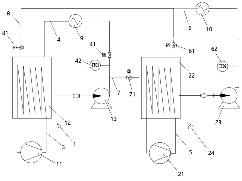
[0023] Such as figure 1 As shown, a chiller unit suitable for a hydrogenation station of the present invention includes a compressor chiller unit 1 and a hydrogenation machine chiller unit 2;

[0024] The compressor chiller unit 1 includes a first refrigeration compressor 11, a first evaporator 12, and a first water pump 13. The first refrigeration compressor 11 and the first evaporator 12 form a closed loop through the first pipeline 3. The first heat exchange The shell side of the device 9 and the first evaporator 12 form a closed circuit through the second pipeline 4, the tube side of the first heat exchanger 9 is connected with the hydrogen source after the pressurization of the compressor, and the first water pump 13 ...


PUM


Abstract

The invention discloses a water chilling unit suitable for a hydrogen refueling station. The water chilling unit comprises a compressor water chilling unit and a hydrogen refueling machine water chilling unit. A first evaporator and a second evaporator form a closed loop through a connecting pipeline, the connecting pipeline comprises a first connecting pipe and a second connecting pipe, one end of the first connecting pipe is communicated with the second pipeline and located between the first water pump and the first valve, the other end of the first connecting pipe is communicated with the second evaporator, a third valve is arranged on the first connecting pipe, one end of the second connecting pipe is communicated with the first evaporator, the other end of the second connecting pipe is communicated with the fourth pipeline and located between the second heat exchanger and the second valve, and the fourth valve is arranged on the second connecting pipe. The using method of the water chilling unit suitable for the hydrogen refueling station is characterized by comprising three working modes, namely a compressor heat exchange mode, a hydrogen refueling machine heat exchange mode and a linkage working mode. According to the invention, the compressor water chilling unit and the hydrogen refueling machine water chilling unit are integrated, so that the hydrogen refueling time can be shortened.

Description

technical field [0001] The invention relates to the technical field of hydrogen refueling stations, in particular to a chiller suitable for hydrogen refueling stations and its usage method. Background technique [0002] The chillers equipped in existing hydrogen refueling stations are not specially suitable for hydrogen refueling stations. Usually, separate chillers are required for compression equipment and hydrogen refueling machines. According to the actual operating conditions of hydrogen refueling stations at this stage, due to the Soon, the requirement for the hydrogenation machine chiller is to provide a large amount of cooling capacity for heat exchange in a short period of time, and at the same time the outlet water temperature should be lower than normal temperature. If the hydrogenation machine chiller is in real-time standby state, it will consume a lot of power , and in the shutdown state, although it can save electric energy, it takes a certain amount of time t...

Claims


Application Information

Patent Timeline
Patent Type & Authority Applications(China)
IPC IPC(8): F17D1/08F17D3/01F17D5/00F17C13/00
CPCF17D1/082F17D3/01F17D5/00F17C13/00F17C2270/0134Y02E60/32
Inventor 方沛军姜方宣锋张晓飞伍远安曹俊
Owner 上海氢枫能源技术有限公司
Why Eureka
Try Eureka