
Cooling method for new energy automobile machining

A new energy vehicle and processing seat technology, which is applied in lighting and heating equipment, household appliances, household refrigeration devices, etc., can solve the problems of not having processing machinery and object workbench cooling, and having no device for emergency cooling, so as to achieve good heat dissipation effect, the effect of ensuring dredging

Inactive Publication Date: 2021-11-05
史庆焕
View PDF0 Cites 0 Cited by
  • Summary
  • Abstract
  • Description
  • Claims
  • Application Information

AI Technical Summary

Problems solved by technology

[0004] Aiming at the deficiencies of the prior art, the present invention provides a cooling method for the processing of new energy vehicles, which solves the problem that most of the existing processing machines do not have the function of cooling the processing machines and object workbenches, nor do they have an emergency effect on the whole device. The problem of the ability to cool down

Method used


Image

  • Cooling method for new energy automobile machining
  • Cooling method for new energy automobile machining
  • Cooling method for new energy automobile machining

Examples


Embodiment example 1

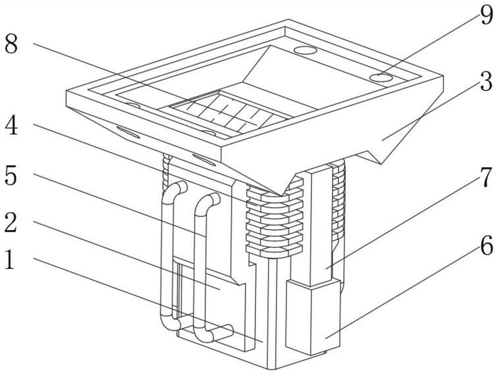
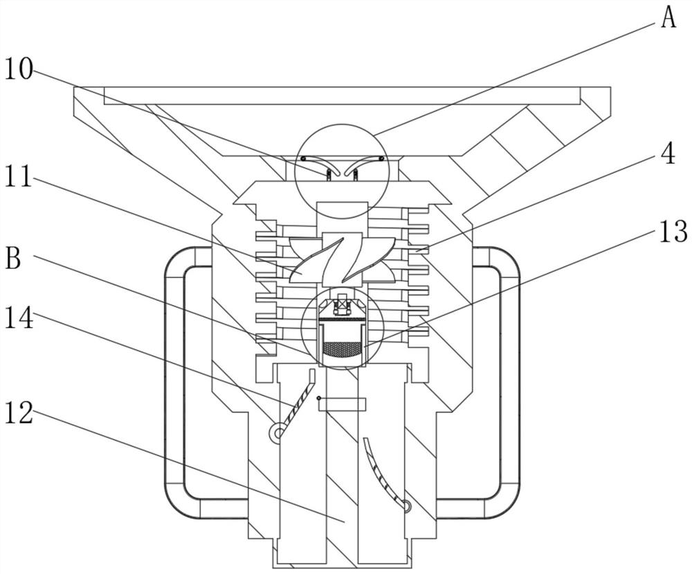
[0033] see Figure 1-5 , the present invention provides a technical solution: a cooling device for processing new energy vehicles, including a bottom shell 1, a heat conduction shell 2 is arranged on the outside of the bottom shell 1, and a heat dissipation fin tube 4 is arranged above the bottom shell 1, A cooling processing seat 3 is provided on the top of the connection heat conduction shell 2, and a water tank 6 is provided on the side of the bottom shell 1 adjacent to the connection heat conduction shell 2, and a connection reinforcement 7 is provided above the water tank 6, and an injection water pump is provided inside the water tank 6 to connect heat conduction The outer shell 2 is provided with a return liquid pipe 5, the bottom of the return liquid pipe 5 is connected with the water tank 6, the water outlet of the injection pump is connected with the water inlet of the heat dissipation fin pipe 4, and the cooling processing seat 3 is provided with a material drop-off ...

Embodiment example 2

[0041] A cooling method for processing new energy vehicles, comprising the following cooling steps:

[0042] S1: place the cooling equipment as a whole under the processing table, align the upper workbench and set it, insert the workbench above the part into the docking hole 9 of the cooling processing seat 3 through the installation rod, and complete the docking of the device;

[0043] S2: The upper processing table guides the heat of processing to the lower connected heat conduction shell 2 through the cooling processing seat 3, and the internal circulating water cools down through the cooling fin tube 4;

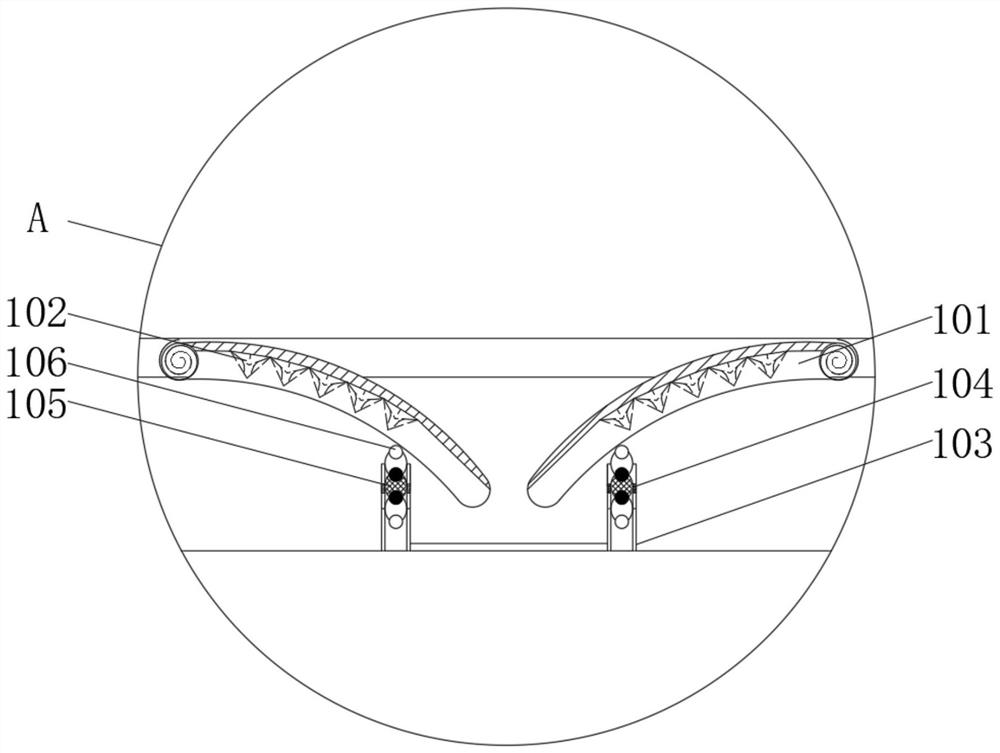
[0044] S3: The upper internal position adjustment device 10 will be used to limit the whereabouts of the processing residual materials above. When the weight is too large, or when there are many accumulated materials, the columnar electromagnet positioner 103 is pressed down at this time. When the energized contact column 105 is pressed down and does not contact the inner...


PUM


Abstract

The invention discloses cooling equipment for new energy automobile processing. The cooling equipment comprises a bottom shell, wherein a connecting heat-conducting shell is arranged on the outer side of the bottom shell, and a radiating finned tube is arranged above the bottom shell; a cooling processing seat is arranged at the top of the connecting heat-conducting shell, and a water tank is arranged on the side face, adjacent to the connecting heat-conducting shell, of the bottom shell; a connecting reinforcing piece is arranged above the water tank, and an injection water pump is arranged in the water tank; a backflow liquid pipe is arranged on the outer side of the connecting heat-conducting shell; and the bottom of the backflow liquid pipe communicates with the water tank. The invention relates to the technical field of new energy automobiles. According to the cooling equipment for new energy automobile machining, the purpose of cooling new energy automobile machining equipment is achieved, and the whole cooling equipment further has a good radiating effect when materials on the upper portion fall off; and when the whole cooling equipment works, the purpose of technical radiating can be achieved under the emergency condition.

Description

technical field [0001] The invention relates to the technical field of new energy vehicles, in particular to a cooling method for processing new energy vehicles. Background technique [0002] New energy vehicles refer to the use of unconventional vehicle fuels as power sources (or the use of conventional vehicle fuels, the use of new vehicle power devices), integrated vehicle power control and advanced technology in driving, the formation of advanced technical principles, with Auto parts processing is the unit that constitutes the overall processing of auto parts and the products that serve the processing of auto parts. As the foundation of the auto industry, auto parts are a necessary factor to support the sustainable and healthy development of the auto industry. The automobile industry is developing and innovating independently, and needs a strong parts system to support it. Most of the existing auto parts processing equipment does not have adjustment functions, and the de...

Claims


Application Information

Patent Timeline
Patent Type & Authority Applications(China)
IPC IPC(8): F25D31/00
CPCF25D31/00
Inventor 史庆焕
Owner 史庆焕
Learn More