Textile air permeability detector

A gas permeability and detector technology, applied in the field of textiles, can solve problems affecting detection accuracy, detection position sealing, and air permeability detection accuracy, and achieve the effect of increasing test accuracy

Active Publication Date: 2021-11-05
南通新彤进出口有限公司
View PDF7 Cites 0 Cited by
  • Summary
  • Abstract
  • Description
  • Claims
  • Application Information

AI Technical Summary

Problems solved by technology

[0003] Existing testing devices for air permeability of textiles generally use the air flow through the fabric to test the air permeability, but the existing monitoring mechanism cannot seal the testing position before testing the fabric, resulting in air leakage, affecting the detecti

Method used


Image

  • Textile air permeability detector
  • Textile air permeability detector
  • Textile air permeability detector

Examples


Embodiment 1

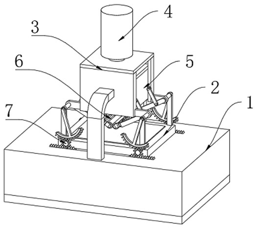
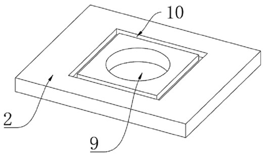
[0032] see figure 1As shown, a textile air permeability tester includes an installation base 1, a processing table 2 is fixedly connected to the middle position of the top of the installation base 1, and a ventilation slot 9 is opened in the middle position of the processing table 2, and the upper surface of the processing table 2 is opposite to The outer edge of the ventilation slot 9 is provided with a sealing groove 10, and the top of the installation base 1 is fixedly connected to the limit housing 3 relative to the upper position of the processing table 2. The top of the limit housing 3 is fixedly installed with a hydraulic cylinder 4, and the hydraulic cylinder 4 The bottom of the bottom extends to the inner cavity of the limit housing 3, and a sealing cover 5 is fixedly installed on the bottom. The sealing cover 5 is a hollow structure. The size of the outer wall of the bottom of the sealing cover 5 is the same as the inner diameter of the sealing groove 10. Spread the ...

Embodiment 2

[0034] see Figure 6 As shown, it is basically the same as Embodiment 1, furthermore, the left and right sides of the sealing cover 5 are provided with a smoothing mechanism 6, taking the right side wall smoothing mechanism 6 as an example, the smoothing mechanism 6 includes a mounting block 22 , the mounting block one 22 is provided with two groups, fixedly installed on the front and rear sides of the right side wall of the sealing cover 5 respectively; There is smoothing mechanism 6 movably connected between the inwalls of two 24, movable plate 23 is movably connected between the inwall upper side of smoothing mechanism 6 and the inwall of installation piece one 22, and the outer wall of installation piece two 24 is movably connected with rotating shaft 26, The rotating shaft 26 is located at the axial center where the mounting frame 25 is connected to the second mounting block 24 , and the rotating shaft 26 is coaxially fixedly connected with the mounting frame 25 .

[003...

Embodiment 3

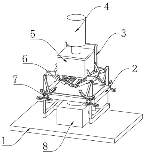
[0038] see Figure 8 As shown, it is basically the same as the second embodiment, and furthermore, the inner cavity of the installation base 1 is fixedly equipped with an inflatable mechanism 8, and the inflatable mechanism 8 includes a gas storage shell one 37, and the middle position of the inner cavity of the gas storage shell one 37 is An air bag 40 is fixedly installed, and the embedded side of the air bag 40 is provided with a spring 2 41 horizontally. The top of the air bag 40 is provided with a one-way valve connected from the inside to the outside, and the bottom of the air bag 40 is provided with a one-way valve connected from the outside to the inside. The inner cavity of housing one 37 is provided with pressing plate 38 relative to the left and right sides of airbag 40, and the side of pressing plate 38 away from airbag 40 is fixedly connected with push rod one 39, and the side of push rod one 39 away from pressing plate 38 is fixedly connected with push plate 36 ....


PUM


Abstract

A textile air permeability detector is disclosed in the invention, and comprises a mounting base, a processing table is fixedly connected to the middle position of the top of the mounting base, a ventilation groove hole is formed in the middle position of the processing table, and a sealing groove is formed in the position, opposite to the outer edge of the ventilation groove hole, of the upper surface of the processing table; and a limiting shell is fixedly connected to the position, opposite to the upper portion of the machining table, of the top of the mounting base, a hydraulic cylinder is fixedly mounted at the top of the limiting shell, the bottom of the hydraulic cylinder extends to an inner cavity of the limiting shell, and a sealing cover is fixedly mounted at the bottom of the hydraulic cylinder. A first straight rack drives a first gear to deflect anticlockwise when moving upwards, then a pointer is driven to deflect on the outer wall of a dial, and due to the fact that the sealing cover and the limiting shell are both made of a transparent structural material, the value of air pressure entering the inner cavity of the sealing cover can be directly read by directly observing the deflection angle of the pointer on the outer wall of the dial, so the air permeability of the cloth is indirectly obtained.

Description

technical field [0001] The invention relates to the technical field of textiles, in particular to a textile air permeability tester. Background technique [0002] Air permeability is a physical index that characterizes the permeability of air in the tested sample, mainly for porous materials and other materials with large air permeability, such as textiles, sponges, leather, etc. For fabric materials, the air permeability is related to the number and size of warp and weft yarn gaps and fiber gaps in the fabric, warp and weft density, yarn twist, fiber properties, yarn structure, fabric thickness and other factors. [0003] Existing testing devices for air permeability of textiles generally use the air flow through the fabric to test the air permeability, but the existing monitoring mechanism cannot seal the testing position before testing the fabric, resulting in air leakage, affecting the detection accuracy, and The fabric cannot be smoothed, and the wrinkled fabric also a...

Claims


Application Information

Patent Timeline
IPC IPC(8): G01N7/10G01N15/08
Inventor 李丹
Owner 南通新彤进出口有限公司
Why Eureka
Try Eureka