ICP plasma etching equipment capable of increasing plasma density

A plasma and etching equipment technology, applied in the field of plasma etching equipment, can solve the problems of waste of body space, poor etching effect, poor heat dissipation effect, etc., to achieve better practicability, improve quality, and facilitate The effect of real-time monitoring

Pending Publication Date: 2021-11-05
江苏籽硕科技有限公司
View PDF1 Cites 0 Cited by
  • Summary
  • Abstract
  • Description
  • Claims
  • Application Information

AI Technical Summary

Problems solved by technology

[0005] The purpose of the present invention is to provide a kind of ICP plasma etching equipment that can increase the plasma density, possess the setting of spiral groove, make the substrate can rotate, so that the plasma can be more uniformly bombarded on the surface of the substrate, The etching effect is better, and at the same time cooperate with the blowing part and the heat exchange part to dissipate the heat that has not been dissipated by the nitrogen heat dissipation method, and then dissipate the heat again, and rotate the baffle first, and then move it laterally, so that not only the substrate can be shielded, At the same time, the baffle will not occupy much space during the movement process, which has better practical effect, and solves the problem that the ion bombardment may appear unevenly on the surface of the substrate, resulting in poor etching results. At the same time, when the body is used for a long time, the heat dissipation effect is not good, which may cause the device to fail to operate. At the same time, when the baffle is set to block the unstable ion beam, a large rotation area is often required, which is a waste of time. There is a lot of space in the body, resulting in poor practicality

Method used


Image

  • ICP plasma etching equipment capable of increasing plasma density
  • ICP plasma etching equipment capable of increasing plasma density
  • ICP plasma etching equipment capable of increasing plasma density

Examples


Embodiment Construction

[0025] The following will clearly and completely describe the technical solutions in the embodiments of the present invention with reference to the accompanying drawings in the embodiments of the present invention. Obviously, the described embodiments are only some, not all, embodiments of the present invention. Based on the embodiments of the present invention, all other embodiments obtained by persons of ordinary skill in the art without making creative efforts belong to the protection scope of the present invention.

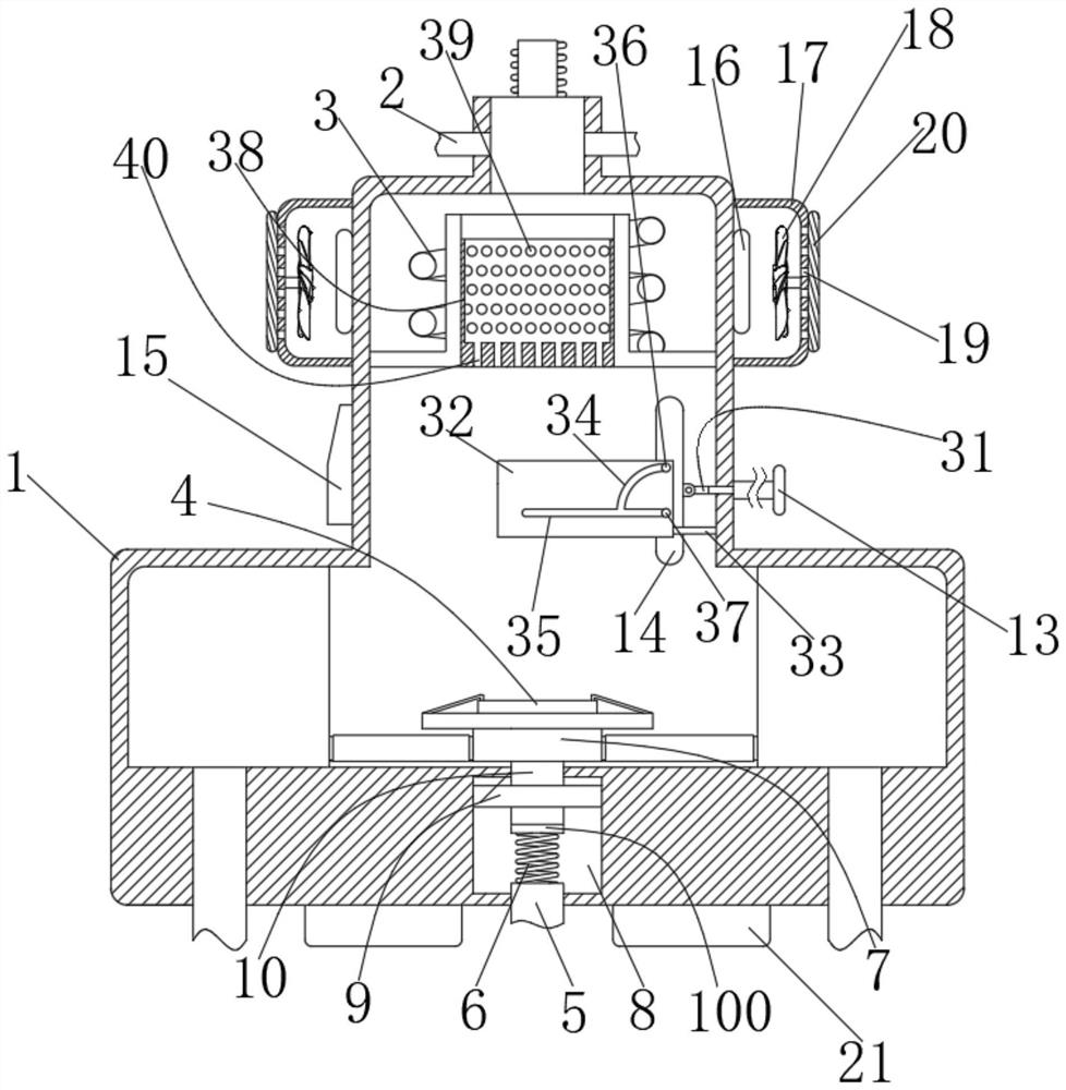
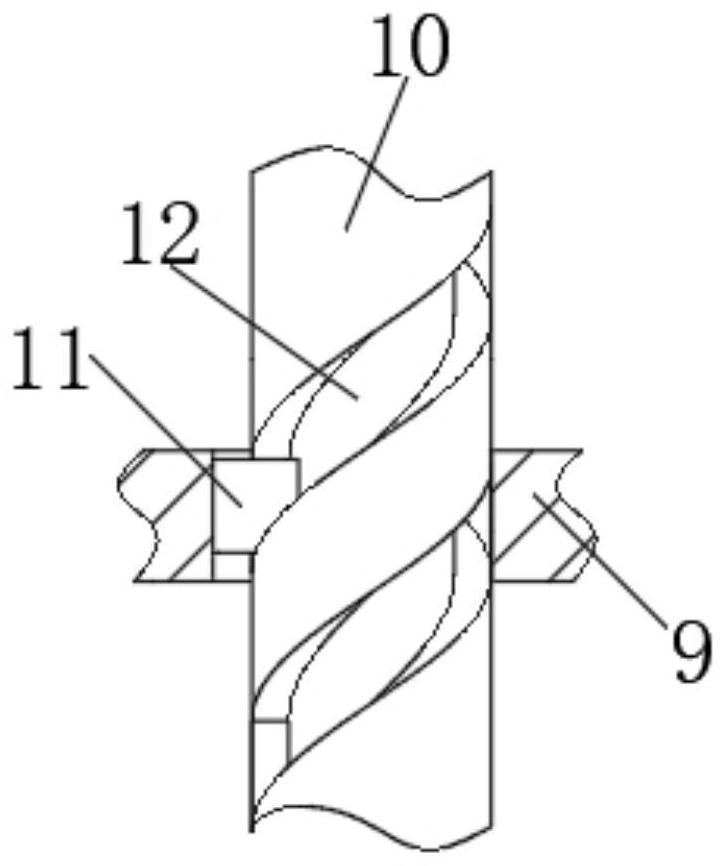
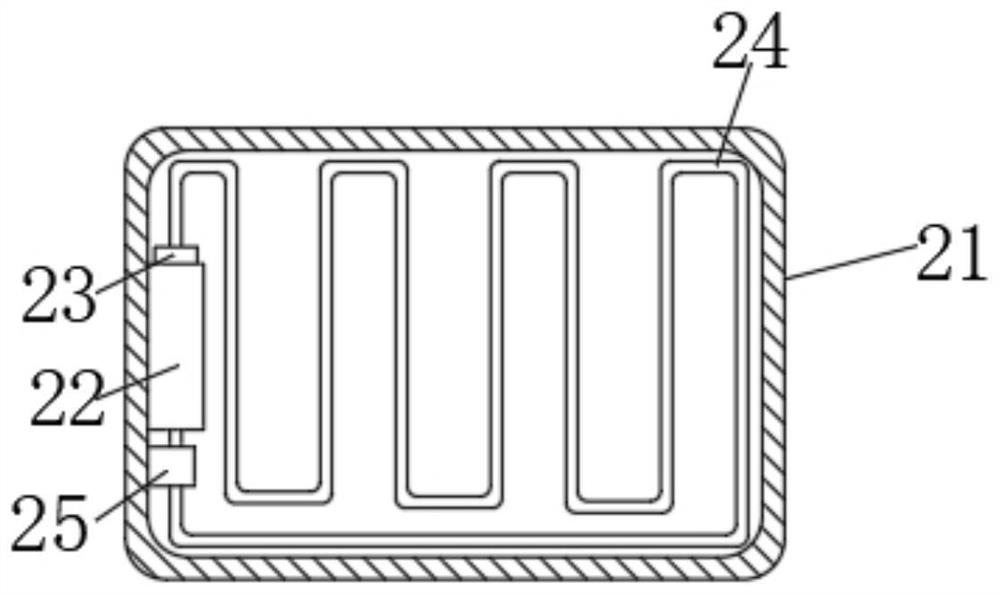
[0026] see Figure 1 to Figure 5, the present invention provides a technical solution: an ICP plasma etching equipment that can increase plasma density, including a body 1, an air inlet 2, a coupling coil 3, a substrate 4, a heat dissipation pipe 5, a spring 6 and a substrate base 7. The inner wall of the body 1 is provided with a fixed opening 8, the upper surface of the spring 6 is provided with a connecting block 100, and the upper surface of the connecting...


PUM


Abstract

The invention discloses ICP plasma etching equipment capable of increasing plasma density, and relates to the technical field of semiconductor manufacturing. The inner wall of a clamping block is fixedly connected with a sliding block, the surface of a rotating block is provided with a spiral groove, the sliding block is in sliding connection with the spiral groove, and a shielding mechanism for shielding a substrate is arranged on the inner wall of a machine body. According to the invention, through the arrangement of the spiral groove, the substrate can be rotated, so that the plasma can be uniformly bombarded on the surface of the substrate, and the etching effect is better; heat which is not completely dissipated by a nitrogen heat dissipation method is dissipated again in cooperation with the blowing component and the heat exchange component, and a baffle plate is rotated firstly and then transversely moved, so that the substrate can be shielded; and meanwhile, the baffle does not occupy much space in the moving process, and the effect of better practicability is achieved.

Description

technical field [0001] The invention relates to the technical field of semiconductor manufacturing, in particular to an ICP plasma etching device capable of increasing plasma density. Background technique [0002] Etching is used in semiconductor manufacturing, and ICP plasma is also called inductively coupled plasma. [0003] For example, a kind of ICP plasma etching machine disclosed in Chinese patent CN202011300038.2 includes a body, the upper surface of the body is fixedly installed with a connecting pipe, and both sides of the connecting pipe are fixedly installed with an air inlet, the body, the connecting pipe, and the air inlet The top of the body is fixedly installed with an iron core, the outer part of the iron core is fixedly connected with a wire, the upper part of the body is fixedly connected with a shielding tube, and the outer part of the shielding tube is fixedly connected with a coupling coil. The ICP plasma etching When increasing the current of the coupl...

Claims


Application Information

Patent Timeline
Patent Type & Authority Applications(China)
IPC IPC(8): H01J37/32H01L21/67
CPCH01J37/321H01J37/3244H01J37/32449H01J37/32522H01J37/32752H01J37/3266H01L21/67069H01J2237/334H01J2237/3343
Inventor 任斌王乃雷
Owner 江苏籽硕科技有限公司
Why Eureka
Try Eureka