Handle and conveyor for realizing quick and slow release of interventional stent

A handle and speed technology, applied in the field of medical devices, can solve the problems that the handle does not have a locking function, interfere with the operator's observation of the image screen, and cannot guarantee the stability of the relative fixed position, etc., to achieve the effect of convenient operation and quick release

Pending Publication Date: 2021-11-09
北京有卓正联医疗科技有限公司
View PDF0 Cites 2 Cited by
  • Summary
  • Abstract
  • Description
  • Claims
  • Application Information

AI Technical Summary

Problems solved by technology

[0006] At present, the conveyor handle with fast and slow release functions requires the operator to visually confirm the position of the handle due to the directional switching method, and sometimes needs to rotate the handle until the switch button is in the ideal operating position, which seriously interferes with the operator's observation of the video screen
And the handle does not have a locking function, which cannot guarantee the stability during transportation and the relatively fixed positions of the outer sheath, TIP head and core tube during withdrawal

Method used


Image

  • Handle and conveyor for realizing quick and slow release of interventional stent
  • Handle and conveyor for realizing quick and slow release of interventional stent
  • Handle and conveyor for realizing quick and slow release of interventional stent

Examples


Embodiment 1

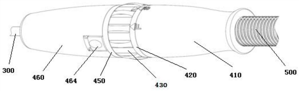
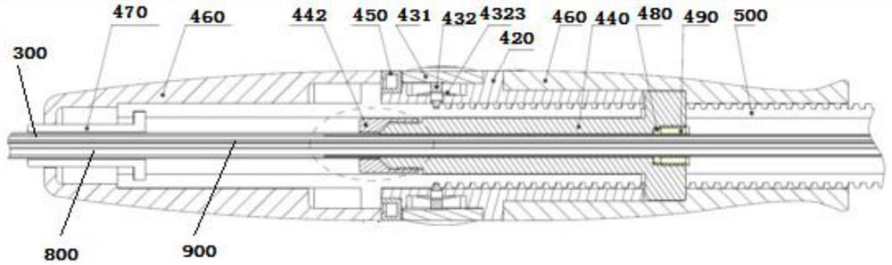
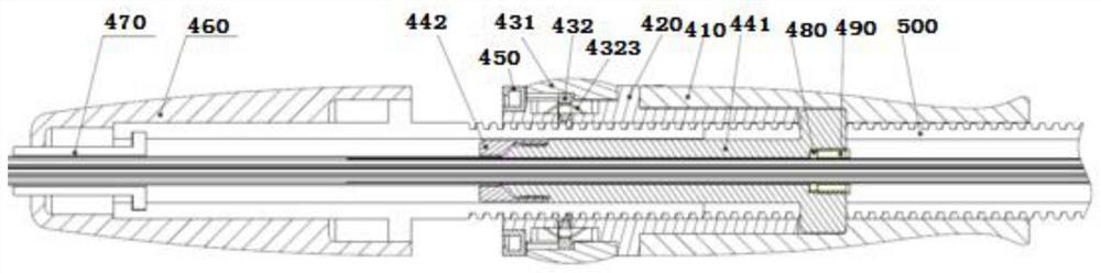
[0049] A handle that realizes the fast and slow release of the interventional support, including a handle housing 410 and a screw sleeve 420 fixed in the handle housing 410, one end of the handle housing 410 ( Figure 1-3 The proximal end) has an axial extension of the screw sleeve 420, and a cam ring speed switching mechanism 430 is arranged on the axial extension.

[0050] The cam ring speed switching mechanism 430 includes a cam ring 431 and a telescopic tooth plate 432 . The cam ring 431 is sleeved on the screw sleeve 420 with a clearance fit therebetween. Along the radial direction of the cam ring 431 , the retractable tooth plate 432 has a tooth body 4321 extending inward. The tooth body 4321 is preferably an internal trapezoidal thread matched with the trapezoidal thread of the screw.

[0051] The outer surface of the telescopic tooth plate 432 is in conflict with the concave-convex inner surface of the cam ring 431; The threads on the screw rod 500 provided inside a...

Embodiment 2

[0058] Different from the above-mentioned embodiments, such as Figure 5-7 As shown, the inner hole of the cam ring 431 has a pair of shallow arc-shaped grooves 4311 and a pair of deep arc-shaped grooves 4312 symmetrically distributed along the circumferential center, forming the concave-convex inner surface. The radial groove depth of the shallow arc-shaped groove 4311 is R1, the radial groove depth of the deep arc-shaped groove 4312 is R2, and the difference between the radial groove depths of the shallow arc-shaped groove 4311 and the deep arc-shaped groove 4312 is not less than the stated The height of the tooth body 4321, that is, R2-R1≥the height of the tooth body 4321. Preferably R2-R1=the height of the tooth body 4321 .

[0059] Preferably, the shallow arc groove 4311 and the deep arc groove 4312 extend in the axial direction, and the angle between them is 50°, that is, the angle at which the cam ring 431 can rotate is 50°.

[0060] Preferably, the cam ring 431 is a ...

Embodiment 3

[0077] A conveyor for fast and slow release of interventional stents, such as Figure 18 As shown, it includes a guide head 100, a sheath tube 300, a screw 500 and the above-mentioned handle; from the proximal end to the distal end, the screw 500 includes a first positioning shaft 510, a button shoulder 520 and a trapezoidal thread shaft 530, the arc The ferrule is fixed on the first positioning shaft 510 and flush with the distal end of the button shoulder 520; the screw sleeve 420 is slidably sleeved on the trapezoidal threaded shaft 530; the button shoulder 520 corresponds to The position of the button 464 is provided with a button groove 521, so that the free end of the button 464 can be inclined inwardly to slide out or snap into the snap ring 450; The axial through hole is clearance fit with the outer cylindrical surface of the sheath joint 441 . The trapezoidal threaded shaft 530 is provided with a sheath joint guide groove 531 along the axial direction. The sheath tu...


PUM


Abstract

According to a handle and a conveyor for achieving quick and slow release of an interventional stent, by arranging a screw rod, a screw rod sleeve and a cam ring quick and slow switching mechanism, slow and quick release and convenient switching of the stent can be achieved. No matter which release state the handle is in, a reed of a telescopic tooth plate of the cam ring fast and slow switching mechanism always jacks a tooth plate to the deep arc-shaped groove position or the shallow arc-shaped groove position, so that the tooth plate can switch fast and slow release states only when the cam ring is manually shifted, and the whole handle is safe and reliable to use. A clamping hook and a clamping ring can be separated and unlocked by pressing a button on an arc-shaped clamping sleeve, so that a sheath tube and a guide head can be separated; after the interventional stent is released, the arc-shaped clamping sleeve, the clamping hook and the clamping ring are withdrawn to be hooked and locked again, so that when the whole conveyor is withdrawn, the guide head and the rear release mechanism cannot be separated from the sheath tube, a situation that the rear release mechanism scratches the intima is avoided, and a situation that the sheath tube, the rear release mechanism and the guide head are suddenly changed in size and difficult to operate when being withdrawn from the femoral artery incision in sequence is avoided.

Description

technical field [0001] The invention relates to the technical field of medical devices, in particular to a handle and a conveyor for realizing fast and slow release of an interventional stent. Background technique [0002] Aortic dissection is an acute aortic disease with a dangerous condition, rapid progress and high mortality, and its incidence accounts for about 5% to 20% of the general population. For lesions confined to the descending aorta, interventional stent-graft surgery is the main treatment option in clinical practice, that is, the stent-graft is pressed and held in the transporter, and is delivered along the guide wire through the femoral artery puncture / incision approach. At the lesion site, the outer sheath of the delivery device is withdrawn, and the stent graft is self-expanding and opens, attaching to the vessel wall, and isolating the blood flow in the aortic dissection or tumor cavity to achieve the purpose of treatment. [0003] The aortic stent graft s...

Claims


Application Information

Patent Timeline
Patent Type & Authority Applications(China)
IPC IPC(8): A61F2/966A61F2/97
CPCA61F2/966A61F2/97
Inventor 于学保许尚栋赵国行伍源付天翔刘冰崔跃
Owner 北京有卓正联医疗科技有限公司
Why Eureka
Try Eureka