
Spatial rotation construction method for steel shed roof structure of ultra-large stadium

A technology for sports venues and construction methods, applied to roofs, building components, building structures, etc., can solve problems such as unfavorable construction costs, quality, safety control, high tire frame installation height, and large amount of high-altitude hoisting, etc., to achieve reduction Reduce the workload of high-altitude hoisting, improve construction efficiency, and improve the effect of safety guarantee

Active Publication Date: 2021-11-09
CHINA CONSTR FOURTH ENG DIV
View PDF7 Cites 2 Cited by
  • Summary
  • Abstract
  • Description
  • Claims
  • Application Information

AI Technical Summary

Problems solved by technology

However, for the construction of the steel structure roof of super-large stadiums, higher requirements are put forward for the existing construction technology, which poses a huge challenge to engineers and technicians
[0003] The steel structure roof of a super-large stadium has the characteristics of large cantilever span, large component size, heavy component weight, and high structural height. High height, large amount of high-altitude hoisting, and difficult welding quality are not conducive to the control of construction cost, quality, and safety
However, the single overall lifting method, overall jacking method, overall hoisting method, and strip or block installation method are difficult to apply to the construction of this type of steel structure roof.

Method used


Image

  • Spatial rotation construction method for steel shed roof structure of ultra-large stadium
  • Spatial rotation construction method for steel shed roof structure of ultra-large stadium
  • Spatial rotation construction method for steel shed roof structure of ultra-large stadium

Examples


Embodiment Construction

[0044] The following will clearly and completely describe the technical solutions in the embodiments of the present invention with reference to the accompanying drawings in the embodiments of the present invention. Obviously, the described embodiments are only some, not all, embodiments of the present invention. Based on the embodiments of the present invention, all other embodiments obtained by persons of ordinary skill in the art without making creative efforts belong to the protection scope of the present invention.

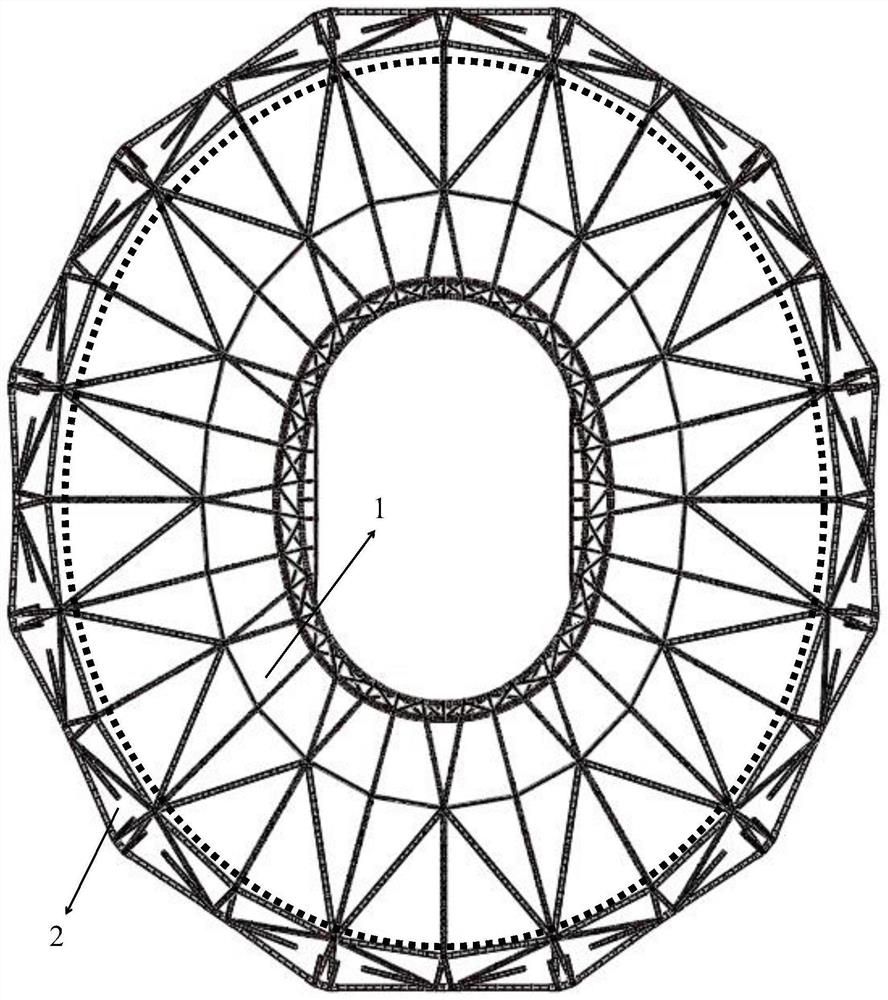
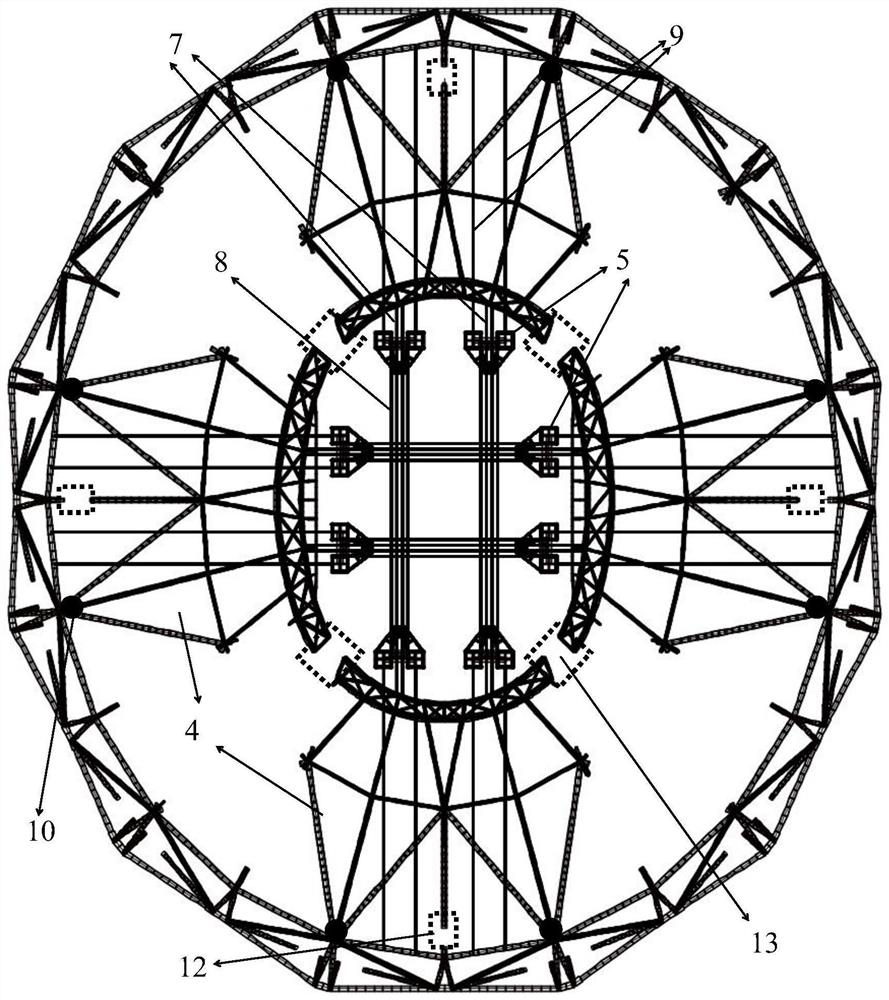
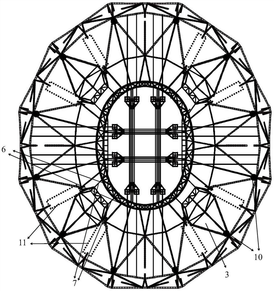
[0045] Please refer to the attached Figure 1-4 , the present invention provides a space swivel construction method for a steel shed roof structure of a super large stadium, comprising: dividing the steel shed roof structure 1 into a single petal swivel unit 3 and a double petal swivel unit 4, and The façade structure 2 forming a closed loop is used as the supporting structure of the swivel unit, and the façade structure 2 and the swivel unit are connected by ...


PUM


Abstract

The invention discloses a spatial rotation construction method for a steel cover shed roof structure of an ultra-large stadium, and belongs to the technical field of constructional engineering. The spatial rotation construction method comprises the steps that a vertical face structure forming a closed ring serves as a supporting structure of a rotation unit, the vertical face structure and the rotation unit are connected through a rotating hinge, and the rotation unit is lifted in place through lifting equipment; in the rotation unit lifting stage, different types of rotation units are lifted in a staged mode, the east-west double-petal rotation units are firstly and symmetrically lifted, then the south-north double-petal rotation units are symmetrically lifted, after an inner pressure ring truss of a roof structure forms a closed ring, the inner pressure ring truss serves as a supporting structure of a single petal rotation unit, and the single petal rotation unit is lifted; and after the rotation unit is lifted, remaining rod pieces are inlayed, unloading construction is carried out, and system conversion of the steel cover shed is completed. The vertical face structure which is closed into the ring is used as the supporting structure of the rotation unit, and favorable conditions are created for steel cover shed roof structure spatial rotation construction.

Description

technical field [0001] The invention belongs to the technical field of construction engineering, and more specifically relates to a space swivel construction method for a super-large stadium steel shed roof structure. Background technique [0002] In recent years, with the continuous emergence of sports venues, their steel structure roofs have also presented complex, diverse, novel and unique features, and have become landmark public buildings. At present, the commonly used methods for the construction of steel structure roofs of sports venues include high-altitude bulk method, high-altitude sliding method, overall lifting method, overall jacking method, overall hoisting method, and strip or block installation method. However, for the construction of the steel structure roof of the super-large stadium, higher requirements are put forward for the existing construction technology, which poses a huge challenge to the engineering and technical personnel. [0003] The steel stru...

Claims


Application Information

Patent Timeline
IPC IPC(8): E04B7/10E04G21/16
CPCE04B7/105E04G21/161E04G21/162
Inventor 陈凯黄晨光贾新卷莫海钊张在晨胡晨晞季永新
Owner CHINA CONSTR FOURTH ENG DIV
Learn More