
Fuel cell cathode recirculation low-temperature starting system and control method thereof

A fuel cell cathode and start-up system technology, which is applied to fuel cells, fuel cell additives, fuel cell heat exchange, etc., can solve the problems of increasing system complexity, serious energy consumption, and reducing performance output, and achieves high-efficiency control efficiency, The effect of reducing the failure rate of low temperature operation and ensuring the operating life

Active Publication Date: 2021-11-09
TONGJI UNIV
View PDF4 Cites 7 Cited by
  • Summary
  • Abstract
  • Description
  • Claims
  • Application Information

AI Technical Summary

Problems solved by technology

[0003] However, at low temperature (<0°C), the water generated by the fuel cell may freeze, and the ice covers the diffusion layer and the catalytic layer, which hinders the gas transport of the reactants, reduces the proton conductivity in the membrane, and reduces the performance output, which in turn affects the stack at low temperature. In order to adapt to the wide use of all-weather and all-regional environments, it is of great significance to accelerate the research on low-temperature cold-start of fuel cells
[0004] The existing technology can be divided into the method of heat preservation and heating. The heat preservation is to maintain the battery temperature above 0°C to avoid the cold start process, but this method consumes a lot of energy and needs to increase the complexity of the system
Heating generally uses PTC or hydrogen catalysis to heat the coolant, such as using hydrogen / oxygen catalytic reaction to release heat and then heat the coolant, but the high temperature heat flow cannot be fully utilized, resulting in a lot of waste, and the concentration of hydrogen may cause safety problems

Method used


Image

  • Fuel cell cathode recirculation low-temperature starting system and control method thereof
  • Fuel cell cathode recirculation low-temperature starting system and control method thereof
  • Fuel cell cathode recirculation low-temperature starting system and control method thereof

Examples


Embodiment

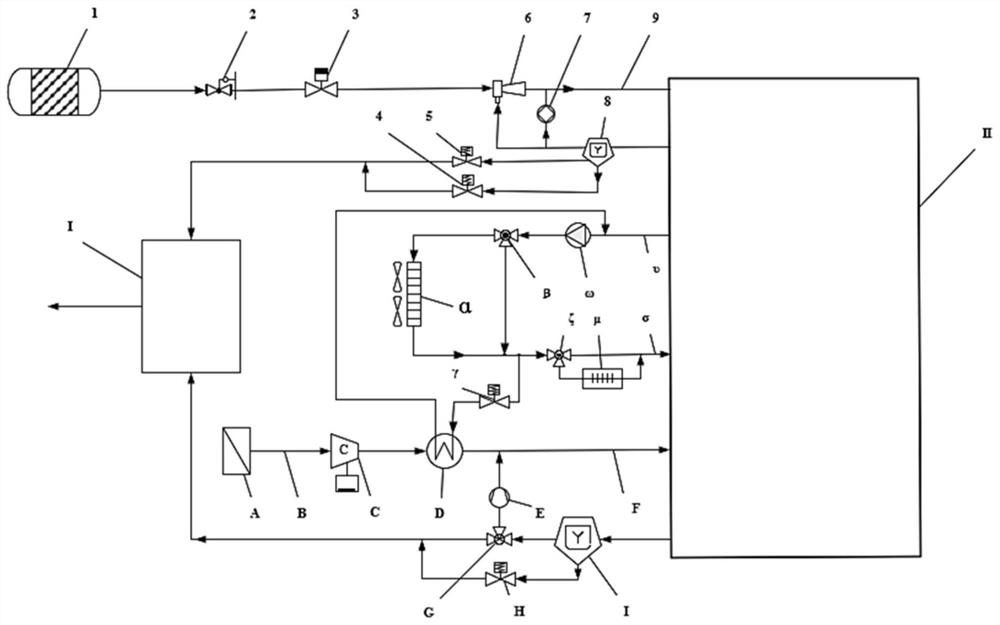
[0042] see figure 1 . It should be noted that the structures, proportions, sizes, etc. shown in the drawings attached to this specification are only used to match the content disclosed in the specification, for those who are familiar with this technology to understand and read, and are not used to limit the implementation of the present invention. Limiting conditions, so there is no technical substantive meaning, any modification of structure, change of proportional relationship or adjustment of size, without affecting the effect and purpose of the present invention, should still fall within the scope of the present invention. Within the scope covered by the disclosed technical content, without substantial changes in the technical content, it should also be regarded as the scope of the present invention that can be implemented.

[0043]The invention relates to a fuel cell cathode recirculation low-temperature start-up system, the fuel cell system includes an air filter A, an ...


PUM


Abstract

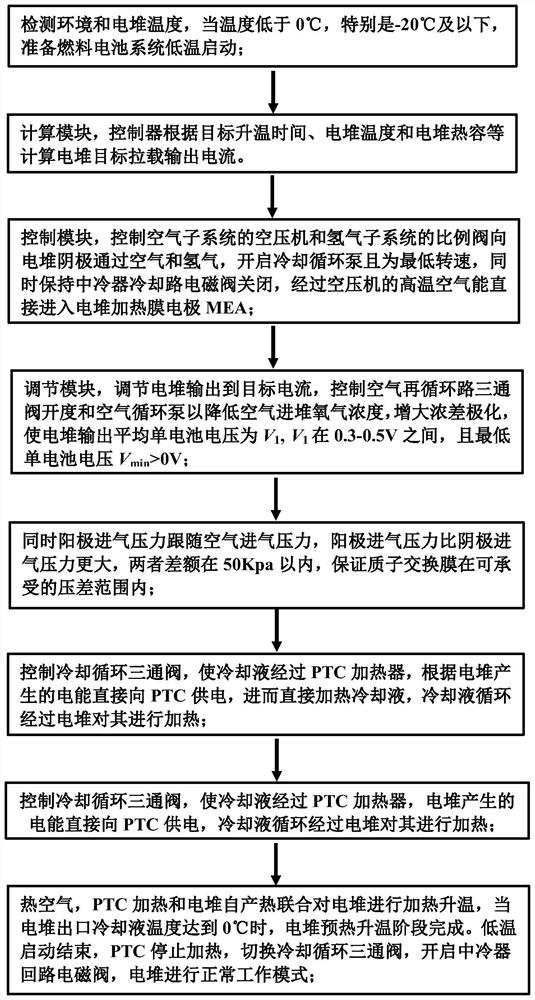
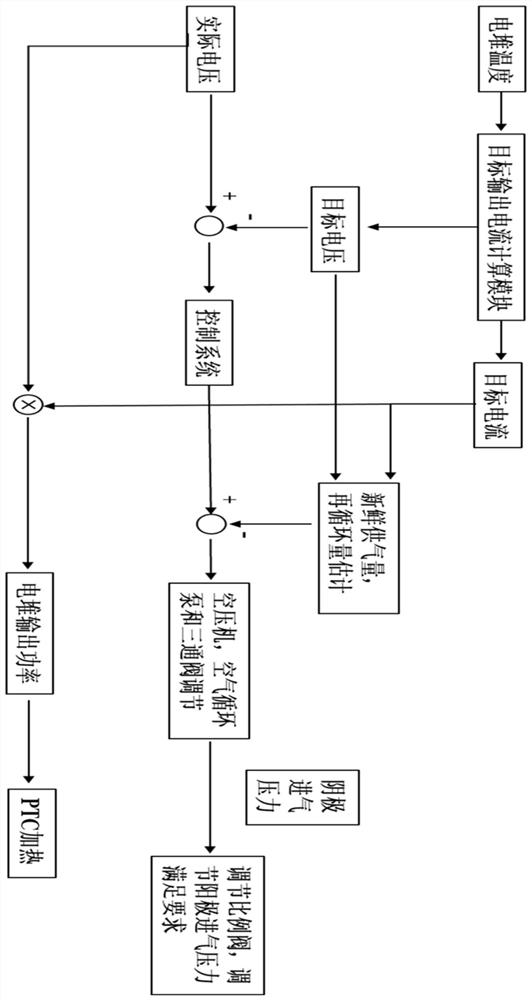
The invention relates to a fuel cell cathode recirculation low-temperature starting system and a control method thereof. The system comprises an air supply subsystem, a hydrogen supply subsystem and a cooling circulation subsystem. Through system control, hot air directly heats an MEA, electric energy output by a galvanic pile enables a PTC to heat cooling liquid, the operation conditions of the galvanic pile are controlled to increase self-produced heat, so that the galvanic pile is jointly heated, energy is utilized to the maximum extent to heat the galvanic pile, and the low-temperature starting capability is enhanced; when the temperature of the cooling liquid at the outlet of the galvanic pile reaches 0 DEG C, the galvanic pile preheating temperature rise stage is completed. Compared with the prior art, the method is beneficial to realizing quick start of the fuel cell in a low-temperature environment, the failure rate of low-temperature start of the fuel cell is reduced, and the service life of the fuel cell at a low temperature is prolonged.

Description

technical field [0001] The invention relates to the technical field of fuel cells, in particular to a fuel cell cathode recirculation low-temperature starting system and a control method thereof. Background technique [0002] A proton exchange membrane fuel cell is an electrochemical power generation device that directly converts the chemical energy of fuel (such as hydrogen) into electrical energy. As long as fuel and oxidant (air or oxygen) are continuously supplied, the fuel cell will continuously output electricity, as well as produce water and heat. It has the advantages of high power generation efficiency, low noise, zero emission and fast dynamic response. It is considered as one of the clean and efficient new energy power generation devices and can be widely used in the automotive field. [0003] However, at low temperature (<0°C), the water generated by the fuel cell may freeze, and the ice covers the diffusion layer and the catalytic layer, which hinders the ga...

Claims


Application Information

Patent Timeline
Patent Type & Authority Applications(China)
IPC IPC(8): H01M8/04007H01M8/04014H01M8/04029H01M8/04082H01M8/04089H01M8/04223H01M8/04225H01M8/04302H01M8/0432H01M8/04746H01M8/04791H01M8/04858
CPCH01M8/04014H01M8/04029H01M8/04037H01M8/04089H01M8/04201H01M8/04225H01M8/04268H01M8/04302H01M8/04753H01M8/0432H01M8/0491H01M8/04798H01M8/0488H01M8/04873H01M8/04783H01M2250/20Y02E60/50
Inventor 许思传刘鹏程
Owner TONGJI UNIV
Learn More