
Circular polarizing plate with anti-reflection layer and image display device using the circular polarizing plate with anti-reflection layer

A technology of image display device and anti-reflection layer, applied in coating, optics, optical components, etc., can solve the problem of uneven hue, achieve high transmittance, optimize in-plane retardation, and suppress uneven hue

Pending Publication Date: 2021-11-12
NITTO DENKO CORP
View PDF6 Cites 0 Cited by
  • Summary
  • Abstract
  • Description
  • Claims
  • Application Information

AI Technical Summary

Problems solved by technology

However, when a circular polarizing plate is applied to an image display device with low reflectance (especially an organic EL display device), there is a problem that it is easy to visually recognize color unevenness

Method used


Image

  • Circular polarizing plate with anti-reflection layer and image display device using the circular polarizing plate with anti-reflection layer
  • Circular polarizing plate with anti-reflection layer and image display device using the circular polarizing plate with anti-reflection layer
  • Circular polarizing plate with anti-reflection layer and image display device using the circular polarizing plate with anti-reflection layer

Examples


Embodiment

[0124] Hereinafter, although an Example demonstrates this invention concretely, this invention is not limited to these Examples. In addition, the measurement method of each characteristic is as follows.

[0125] (1) Reflectivity

[0126] For the antireflection layers used in Examples and Comparative Examples, the front reflectance was measured using a spectrophotometer "CM-2600d" manufactured by Konica Minolta. The front reflectance was measured by the SCI method. The measurement was performed by changing the wavelength of the measurement light between 380 nm and 780 nm, and the wavelength at which the lowest reflectance was observed was taken as the bottom wavelength, and the reflectance at the bottom wavelength was taken as the bottom reflectance.

[0127] (2) Thickness

[0128] The measurement was performed using an interference film thickness meter (manufactured by Otsuka Electronics Co., Ltd., product name "MCPD-3000").

[0129] (3) Refractive index

[0130] The meas...

manufacture example 1

[0143] [Production Example 1: Production of Polarizer]

[0144] A polyvinyl alcohol film having an average degree of polymerization of 2400, a degree of saponification of 99.9 mol %, and a thickness of 45 μm was immersed in warm water at 30° C. for 60 seconds to swell. Next, the film was immersed in an aqueous solution having a concentration of 0.3% of iodine / potassium iodide (weight ratio = 1 / 7), and the film was dyed while being stretched to 2.6 times. Then, it extended|stretched so that the total draw ratio might become 6 times in the 65 degreeC 4weight% boric-acid aqueous solution. After stretching, drying was performed in an oven at 55° C. for 1 minute to obtain a PVA-based polarizer. The polarizer had a thickness of 18 μm and a moisture content of 15 wt %.

manufacture example 2

[0145] [Production Example 2: Production of a retardation film constituting a retardation layer]


PUM

PropertyMeasurementUnit
Thicknessaaaaaaaaaa
Thicknessaaaaaaaaaa

Abstract

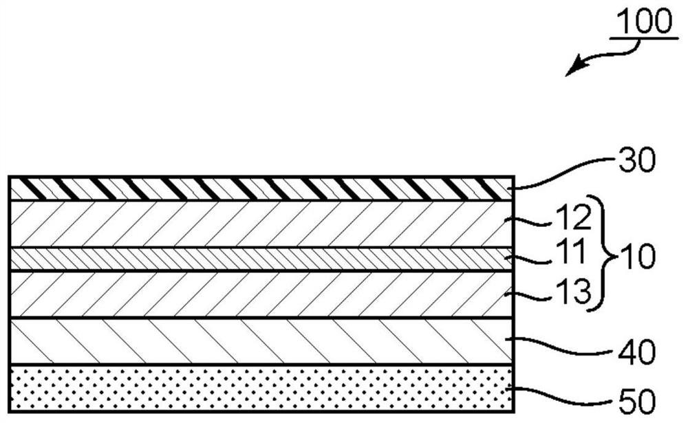
The present invention relates to a circular polarizing plate with an anti-reflection layer and an image display device using the circular polarizing plate with an anti-reflection layer. Provided is the circular polarizing plate with the anti-reflection layer, which can realize the image display device in which color unevenness is suppressed. The circular polarizing plate with an anti-reflection layer has: a polarizing plate including a polarizer, an anti-reflection layer arranged on one side of the polarizing plate and a retardation layer arranged on the other side of the polarizing plate. The refractive index of the anti-reflection layer is 1.29-1.38, and thickness is 70nm-120nm. In the wavelength range of 380 nm to 780 nm, the wavelength at which the lowest reflectance is obtained exists in the range of 400 nm to 600 nm. Re (550) of the retardation layer is 136 nm to 200 nm.

Description

technical field [0001] The present invention relates to a circularly polarizing plate with an antireflection layer and an image display device using the circularly polarizing plate with an antireflection layer. Background technique [0002] In recent years, image display devices represented by liquid crystal display devices and electroluminescence (EL) display devices (eg, organic EL display devices, inorganic EL display devices) are rapidly spreading. In an image display device, a circularly polarizing plate including a polarizing plate and a retardation plate is sometimes used. However, when a circularly polarizing plate is applied to an image display device (especially an organic EL display device) with a low reflectance, there is a problem in that the color unevenness is easily visually recognized. [0003] prior art literature [0004] Patent Literature [0005] Patent Document 1: Japanese Patent No. 5876441 [0006] Patent Document 2: Japanese Patent Laid-Open No. ...

Claims


Application Information

Patent Timeline
IPC IPC(8): G02B5/30G02B1/11G02F1/1335H01L27/32
CPCG02B5/3041G02B1/11G02B5/3083G02F1/133528G02F1/1335H10K59/50G02B5/3033G02B1/04
Inventor 池岛裕美中原步梦桥本尚树尾込大介
Owner NITTO DENKO CORP
Learn More