Discharging cooling system for printing machine

A cooling system and printing press technology, applied in printing presses, general parts of printing machinery, printing and other directions, can solve the problems of reducing the printing effect of the device, the pigment becomes smeared, and easy to adhere, and achieves the promotion of intensity, resource saving, and speeding up. The effect of cooling speed

Active Publication Date: 2021-11-16
南通泽成印务有限公司
View PDF10 Cites 0 Cited by
  • Summary
  • Abstract
  • Description
  • Claims
  • Application Information

AI Technical Summary

Problems solved by technology

[0002] At present, the steps commonly used in the printing production line are paper loading and printing, and packaging starts after the printing is completed. However, for the printed corrugated cardboard, due to the high temperature of the newly printed corrugated cardboard, the printing pigment on the surface is still In order to save space, the corrugated cardboards are usually stacked directly when packing, which will easily cause friction between the corrugated cardboards and make the printed pigments paste, thus reducing the printing capacity of the device. Effect
[0003] Moreover, since the paint on the corrugated cardboard is not dry, the dust in the air is also easy to adhere to the wet paint, resulting in bad defects such as color difference. Therefore, it is necessary to design a blanking cooling system for printing machines to solve the above problems. question

Method used


Image

  • Discharging cooling system for printing machine
  • Discharging cooling system for printing machine
  • Discharging cooling system for printing machine

Examples


Embodiment Construction

[0027] The following will clearly and completely describe the technical solutions in the embodiments of the present invention with reference to the accompanying drawings in the embodiments of the present invention. Obviously, the described embodiments are only some, not all, embodiments of the present invention.

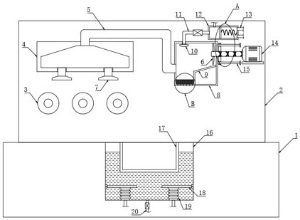
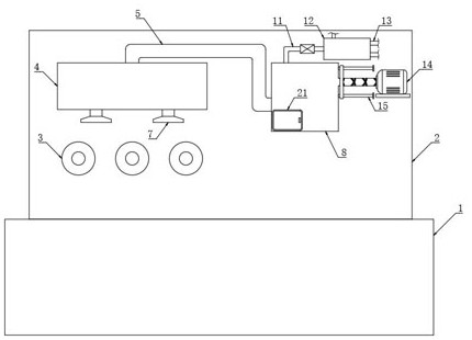
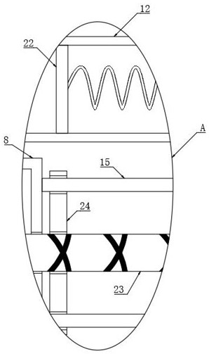
[0028] refer to Figure 1-4 , a blanking cooling system for a printing machine, comprising a workbench 1, a mounting plate 2 is fixedly connected to the upper side wall of the workbench 1, and a plurality of conveying rollers 3 are arranged on the side wall of the mounting plate 2 for conveying printed cardboard.

[0029] The upper side wall of the workbench 1 is provided with a cooling mechanism, the cooling mechanism includes a motor 14, the side wall of the mounting plate 2 is fixedly connected with a placement plate, the motor 14 is fixedly connected to the side wall of the placement plate, and the output shaft of the motor 14 is fixedly connected with a reciproc...


PUM


Abstract

The invention discloses a discharging cooling system for a printing machine. The discharging cooling system comprises a workbench, a mounting plate is fixedly connected to the upper side wall of the workbench, a plurality of conveying rollers are arranged on the side wall of the mounting plate, a cooling mechanism is arranged on the upper side wall of the workbench, the cooling mechanism comprises a motor, an output shaft of the motor is fixedly connected with a reciprocating lead screw, the side wall of the mounting plate is fixedly connected with a mounting box, the reciprocating lead screw extends into the mounting box and is fixedly connected with a plurality of fan blades, the side wall of the mounting plate is fixedly connected with an air suction box, the air suction box communicates with the mounting box through an air guide pipe, and the lower side wall of the air suction box communicates with a plurality of air suction pipes; and a collecting groove is formed in the upper side wall of the workbench. According to the discharging cooling system, the flowing speed of air above corrugated boards can be increased, then the cooling speed of pigments on the corrugated boards is increased, and the situation that the pigments become paste due to mutual friction between the corrugated boards during later stacking is prevented.

Description

technical field [0001] The invention relates to the technical field of printing, in particular to a blanking cooling system for a printing machine. Background technique [0002] At present, the steps commonly used in the printing production line are paper loading and printing, and packaging starts after the printing is completed. However, for the printed corrugated cardboard, due to the high temperature of the newly printed corrugated cardboard, the printing pigment on the surface is still In order to save space, the corrugated cardboards are usually stacked directly when packing, which will easily cause friction between the corrugated cardboards and make the printed pigments paste, thus reducing the printing capacity of the device. Effect. [0003] Moreover, since the paint on the corrugated cardboard is not dry, the dust in the air is also easy to adhere to the wet paint, resulting in bad defects such as color difference. Therefore, it is necessary to design a blanking co...

Claims


Application Information

Patent Timeline
Patent Type & Authority Applications(China)
IPC IPC(8): B41F23/04
CPCB41F23/04
Inventor 于云
Owner 南通泽成印务有限公司
Why Eureka
Try Eureka