Supercharge Your Innovation With Domain-Expert AI Agents!

A method for adjusting and detecting a zoom imaging lens

An imaging lens and detection method technology, applied in installation, instrumentation, optics, etc., can solve problems such as processing errors, low image quality, and low assembly efficiency, and achieve the effects of avoiding repeated disassembly, high measurement accuracy, and simple device structure

Active Publication Date: 2022-08-05
XI'AN INST OF OPTICS & FINE MECHANICS - CHINESE ACAD OF SCI
View PDF14 Cites 0 Cited by
  • Summary
  • Abstract
  • Description
  • Claims
  • Application Information

AI Technical Summary

Problems solved by technology

[0005] The purpose of the present invention is to solve the problems of low image quality, low assembly efficiency and repeated disassembly and assembly of the existing zoom lens due to cam curve processing errors and changes in the attitude of the moving lens group, and provides a zoom imaging lens assembly Adjustment and detection method

Method used


Image

  • A method for adjusting and detecting a zoom imaging lens
  • A method for adjusting and detecting a zoom imaging lens
  • A method for adjusting and detecting a zoom imaging lens

Examples


Embodiment Construction

[0042] The present invention will be described in detail below with reference to the accompanying drawings and specific embodiments. It should be understood by those skilled in the art that these embodiments are only used to explain the technical principle of the present invention, and are not intended to limit the protection scope of the present invention.

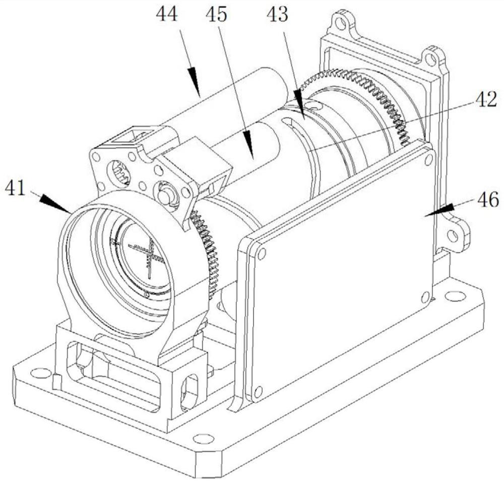
[0043] like figure 1As shown, the existing zoom imaging lens (ie zoom lens 4) includes a main lens barrel 41, a moving lens group 42, a zoom cam 43, a motor 44, a feedback potentiometer 45 and a motor control circuit board 46; the moving lens group 42 is arranged on the The main lens barrel 41 includes a zoom lens group and a compensation lens group. The zoom lens group includes a zoom lens barrel 47 and a zoom lens set in the zoom lens barrel 47. The compensation lens group includes a compensation lens barrel 48 and a set of zoom lenses. For the compensation lens in the compensation lens barrel 48, the zoom cam 43 is in...


PUM


Abstract

The invention provides a method for assembling, adjusting and detecting a zoom imaging lens, which solves the problems of low image quality, low assembly efficiency and repeated disassembly and assembly of the existing zoom lens due to cam curve processing errors and changes in the attitude of the moving lens group. question. This method is an iterative assembling method in which assembly and simulation are synchronized. Through this method, the variation of the attitude of each moving mirror group during the movement process is obtained, and the optical simulation analysis of the variation is performed to evaluate the lens transfer function and the line of sight. At the same time, it can also measure the cam curve of the key parameter of the zoom system, which can more accurately evaluate the performance of the imaging system.

Description

technical field [0001] The invention belongs to the field of zoom optical imaging, in particular to a method for assembling and detecting a zoom imaging lens. Background technique [0002] During the assembly process of the optical lens, it is necessary to ensure that the optical center of each lens glass is coaxial with the mechanical center. When each moving mirror group is static, the centering process can ensure that the optical center is coaxial with the mechanical axis. However, when the moving mirror group moves in the main lens barrel according to the cam curve, the posture of the moving mirror group will change due to the gap between the moving parts, and these changes in the posture will cause the boresight to be out of tolerance and the image plane to be consistent. performance deterioration and other problems, resulting in poor imaging image quality. [0003] When the cam curve directly determines the focal length of the zoom imaging system, the relative positi...

Claims


Application Information

Patent Timeline
Patent Type & Authority Patents(China)
IPC IPC(8): G02B7/02G02B7/04G02B27/62
CPCG02B7/02G02B7/04G02B27/62
Inventor 高波杨洪涛陈卫宁
Owner XI'AN INST OF OPTICS & FINE MECHANICS - CHINESE ACAD OF SCI
Features
  • R&D
  • Intellectual Property
  • Life Sciences
  • Materials
  • Tech Scout
  • Unparalleled Data Quality
  • Higher Quality Content
  • 60% Fewer Hallucinations
Learn More