
A safe and controllable electric drive

An electric transmission and safety technology, applied in the direction of electromechanical devices, electric components, electrical components, etc., can solve the problems of complex cooling system, large speed slip, oil leakage of hydraulic coupling, etc., to improve the driving torque and reduce impurities Remains, the effect of reducing the seriousness of fever

Active Publication Date: 2022-07-15
无锡市亨达电机有限公司
View PDF0 Cites 0 Cited by
  • Summary
  • Abstract
  • Description
  • Claims
  • Application Information

AI Technical Summary

Problems solved by technology

[0005] In order to make up for the deficiencies of the existing technology and solve the need for a complex cooling system during CST operation, oil leakage often occurs during long-term operation of the hydraulic coupling, the speed slip is large, and the efficiency is low; most eddy current motor couplings adopt a disc structure, The loss is large, and complex mechanisms are required to adjust the air gap in order to adjust the torque; the winding permanent magnet governor generally uses brushes and slip rings, which cannot be used in explosion-proof environments and reduces the reliability of the system. A safe and controllable electrical drive

Method used


Image

  • A safe and controllable electric drive
  • A safe and controllable electric drive
  • A safe and controllable electric drive

Examples


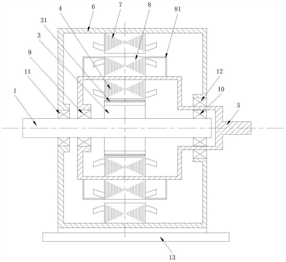
Embodiment 1

[0093] see figure 1 , the present invention provides a safe and controllable electrical transmission device, including a generator unit and a motor unit; the generator unit at least includes an input shaft 1, an output shaft 5, a generator unit with a permanent magnet rotor core 3, a generator unit There are winding rotor core 4, motor unit rotor end winding sheath 2 9 and motor unit rotor end winding sheath 3 10; the motor unit at least includes a motor unit stator casing 6, a motor unit has a winding stator core 7, a motor The unit has a winding rotor core 8, a base 13, a motor unit rotor end winding sheath 4 11 and a motor unit rotor end winding sheath 12; the generator unit and the motor unit share an output shaft 5;

[0094] The base 13 is fixedly connected with the motor unit stator casing 6; the motor unit stator casing 6 is fixedly connected with the motor unit winding stator core 7; the motor unit stator casing 6 is installed with the output shaft 5 together; the mo...

Embodiment 2

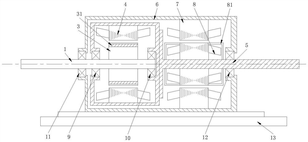
[0096] see figure 2

[0097] The present invention provides a safe and controllable electrical transmission device, including a generator unit and a motor unit; the generator unit at least includes an input shaft 1, an output shaft 5, a permanent magnet rotor core 3 in the generator unit, and a generator unit with a The winding rotor core 4, the motor unit rotor end winding sheath 2 9 and the motor unit rotor end winding sheath 3 10; the motor unit at least includes the motor unit stator casing 6, the motor unit has the winding stator core 7, the motor unit There are winding rotor core 8, base 13, motor unit rotor end winding sheath 4 11 and motor unit rotor end winding sheath 5 12; the generator unit and the motor unit share an output shaft 5;

[0098] The base 13 is fixedly connected with the motor unit stator casing 6; the motor unit stator casing 6 is fixedly connected with the motor unit stator core 7 with windings; the output shaft 5 is set on the motor unit stator cas...

Embodiment 3

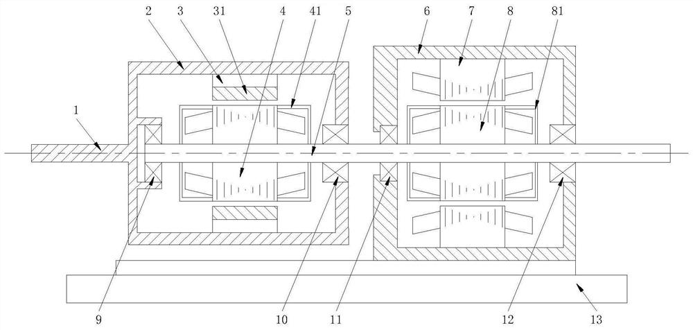
[0100] see image 3

[0101] The present invention provides a safe and controllable electrical transmission device, including a generator unit and a motor unit; the generator unit at least includes an input shaft 1, an output shaft 5, a permanent magnet rotor core 3 in the generator unit, and a generator unit with a The winding rotor core 4, the motor unit rotor end winding sheath 2 9 and the motor unit rotor end winding sheath 3 10; the motor unit at least includes the motor unit stator casing 6, the motor unit has the winding stator core 7, the motor unit There are winding rotor core 8, base 13, motor unit rotor end winding sheath 4 11 and motor unit rotor end winding sheath 5 12; the generator unit and the motor unit share an output shaft 5;

[0102] The base 13 is fixedly connected with the motor unit stator casing 6; the motor unit stator casing 6 is fixedly connected with the motor unit stator core 7 with windings; the motor unit stator casing 6 is internally mounted wi...


PUM


Abstract

The invention belongs to the technical field of electric motors, in particular to a safe and controllable electrical transmission device, comprising a generator unit and a motor unit; the generator unit at least includes an input shaft, an output shaft, and the generator unit has a permanent magnet rotor core. , The generator unit has winding rotor core, motor unit rotor end winding sheath 2 and motor unit rotor end winding sheath 3; after driving equipment (such as motor, heat engine) drives the input shaft of the electrical controllable start transmission device, The electrical controllable starting transmission device can smooth the torque of the output shaft through the external resistance and power electronic converter, and start the load smoothly to the final steady-state speed, so as to avoid the sudden change of the output shaft torque and excessive mechanical failures such as shaft breakage. It is suitable for crushers, fans, water pumps, compressors and other loads, and can reduce the problem of serious heating and small starting torque caused by the long duration of the starting high current of the driving motor.

Description

technical field [0001] The invention belongs to the technical field of electric motors, in particular to a safe and controllable electric transmission device. Background technique [0002] At present, the drive system adopts mechanical coupling or hydraulic coupling to realize torque transmission and speed conversion, which is generally called Controlled Start Transmission (CST), and there are also permanent magnet transmission devices using electromagnetic principles, such as permanent magnet transmission. Magnetic eddy current motor coupler, winding permanent magnet governor, etc. [0003] There are also some technical solutions about motors in the prior art. For example, a Chinese patent with an application number of 981209904 discloses a method and device for controlling an electrical transmission device, and the rotary motion of an electric motor (22) of an electric transmission device (10). By means of a ball screw (26) and a feed nut (28) it is converted into a linea...

Claims


Application Information

Patent Timeline
Patent Type & Authority Patents(China)
IPC IPC(8): H02K3/50H02K1/2753H02K7/18H02K7/10H02K9/06H02P25/02H02P1/26B08B1/00B08B1/04
CPCH02K3/50H02K1/27H02K1/2706H02K7/1807H02K7/10H02K9/06H02P25/02H02P1/26B08B1/32B08B1/12
Inventor 谢鹏程
Owner 无锡市亨达电机有限公司
Learn More