


Quick Research
Generate reliable direction feasibility study reports for your R&D in just a few steps.

Technical Q&A
Discover and master advanced knowledge NOW. Basics, ideas, possibilities, all at once.

Find Solutions
As an expert in R&D theories, this can generate solutions to your technical problems instantly.

Evaluate Feasibility
Analyze your overall solution with one click, know your potential R&D risks in advance.

Monitor Landscape
Get weekly tech updates, stay abreast of the latest tech innovations and key insights.
Barrel type permanent magnet flexible connection device with air gap self-adjusting function
A self-adjusting, soft connection technology, applied in the direction of permanent magnet clutches/brakes, etc., can solve the problems of complex structure and heavy weight of permanent magnet couplers, improve safety and reliability, light weight, reduce slip heat Effect
- Summary
- Abstract
- Description
- Claims
- Application Information
AI Technical Summary
Problems solved by technology
Method used
Image

Examples
Embodiment 1
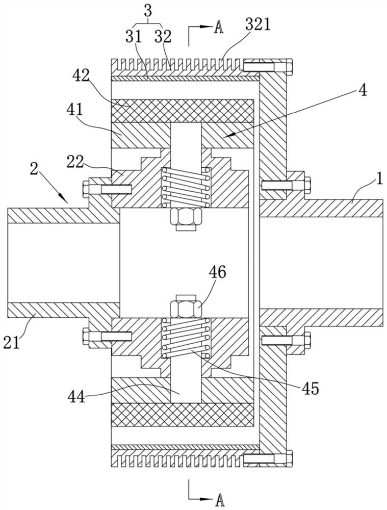
[0043] refer to Figure 1-Figure 4 , the cylindrical self-adjusting air gap permanent magnet soft connection device provided in this embodiment includes:
[0044] The first connecting shaft 1 is suitable for connecting a load;
[0045] The second connecting shaft 2 is suitable for connecting and driving and is coaxial with the first connecting shaft 1;
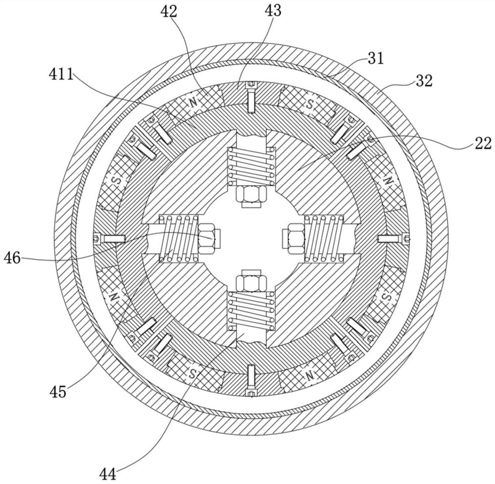
[0046] The conductor rotor 3 includes a conductor ring 31 and a cylindrical conductor ring carrier 32, the conductor ring carrier 32 is relatively fixed on the first connecting shaft 1, and the conductor ring 31 is fixed on the inner wall of the conductor ring carrier 32 above; as known to those skilled in the art, the conductor ring carrier 32, the conductor ring 31 and the first connecting shaft 1 are coaxial; the so-called cylindrical shape is a hollow columnar structure with openings at both ends; "relatively fixed" can be fixed directly or through The connecting piece is indirectly fixed on the first connecting shaft 1,...
Embodiment 2
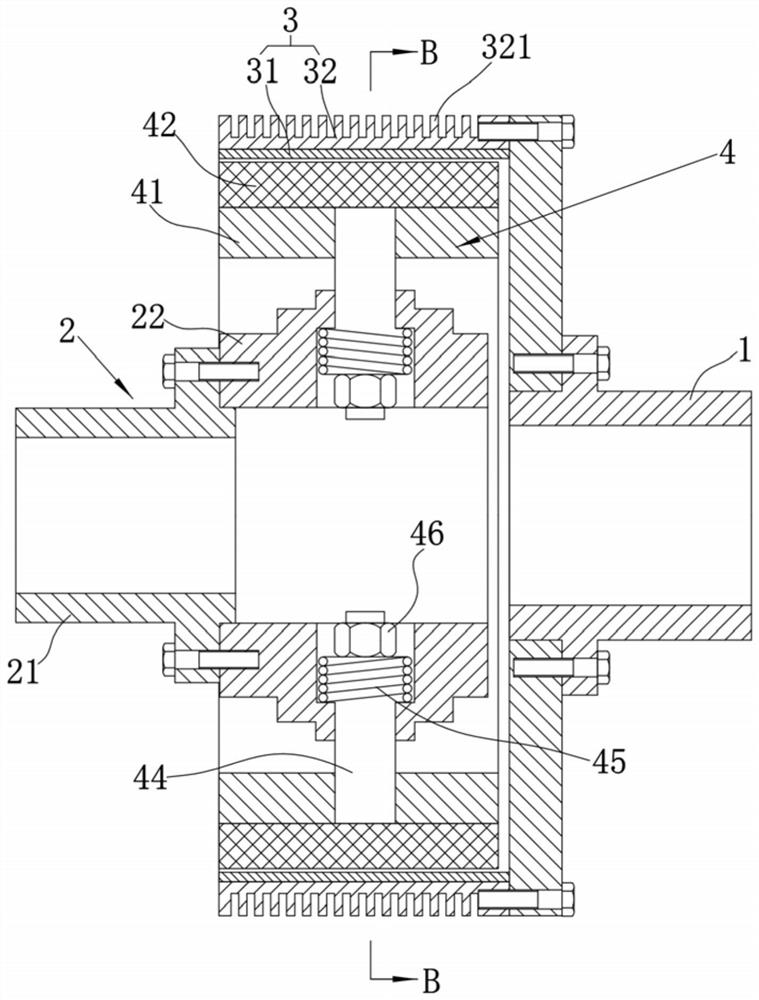
[0075] refer to Figure 5 , the difference between the present embodiment and the first embodiment is only that the installation structure of the elastic member 45 is different, as follows:
[0076] The end face of the second connecting shaft 2 close to the first connecting shaft 1 is sealed and a connecting portion 221 protrudes from the middle, the elastic member 45 is a tensile elastic member, and one end of the elastic member 45 is connected to the carrier block 411 , and the other end of the elastic member 45 is connected to the connecting portion 221 . The tensile force of the elastic member 45 drives the carrier block 411 close to the second connecting shaft 2 , thereby hindering the radial outward movement of the carrier block 411 .
Embodiment 3
[0078] refer to Figure 6-Figure 7 , the difference between the present embodiment and the first embodiment is only that the installation structure of the elastic member 45 is different, as follows:
[0079] The elastic member 45 is a tensile elastic member, and two ends of the elastic member 45 are respectively connected to two adjacent carrier blocks 411 . The tensile force of the elastic member 45 drives two adjacent carrier blocks 411 close to each other. Since the carrier blocks 411 are slidably mounted on the second connecting shaft 2, the carrier blocks 411 will be driven close to the second connecting shaft 2, thus hindering the carrier blocks. 411 moves radially outward.
[0080] Above-mentioned three embodiments have provided three kinds of different installation structures of elastic member 45, and in other embodiments, elastic member 45 can be compression elastic member also can be tension elastic member; Elastic member 45 can adopt such as figure 1 or Figure 5...
PUM
 Abstract
Description
Claims
Application Information
 - R&D Engineer
- R&D Manager
- IP Professional
- Industry Leading Data Capabilities
- Powerful AI technology
- Patent DNA Extraction
Browse by: Latest US Patents, China's latest patents, Technical Efficacy Thesaurus, Application Domain, Technology Topic, Popular Technical Reports.
© 2024 PatSnap. All rights reserved.Legal|Privacy policy|Modern Slavery Act Transparency Statement|Sitemap|About US| Contact US: help@patsnap.com