Movement method of micro-nano motor and directional movement model of micro-nano motor

A directional motion, micro-nano technology, applied in nanotechnology, nanotechnology, nanotechnology for sensing, etc., can solve problems such as the inability to realize directional motion of micro-nano motors

Active Publication Date: 2021-11-16
SOUTH CHINA NORMAL UNIVERSITY +1
View PDF4 Cites 0 Cited by
  • Summary
  • Abstract
  • Description
  • Claims
  • Application Information

AI Technical Summary

Problems solved by technology

However, both of these two methods have the randomness of movement in the three-dimensional direction, that is, the directional movement of the micro-nano motor cannot be realized, which has greatly restricted the practical application of the micro-nano motor

Method used


Image

  • Movement method of micro-nano motor and directional movement model of micro-nano motor
  • Movement method of micro-nano motor and directional movement model of micro-nano motor
  • Movement method of micro-nano motor and directional movement model of micro-nano motor

Examples


Embodiment 1

[0042] This embodiment provides a micro-nano motor, and the preparation process of the micro-nano motor is as follows:

[0043] (1) Take an appropriate amount of SiO with a diameter of 1 μm 2 Microsphere solution in a centrifuge tube, centrifuge;

[0044] (2) Add appropriate amount of ethanol and ultrasonically disperse to obtain SiO 2 ethanol dispersion;

[0045] (3) The dispersed SiO 2 The ethanol dispersion was spread flat on the glass slide, and after the ethanol volatilized, it was placed in a plasma sputtering apparatus for magnetron sputtering. The target material was Au, and the SiO 2 One side surface of the microsphere is sputtered to form an Au layer, the sputtering pressure is 2.0Pa, and the time is 3min;

[0046] (4) After the sputtering is completed, take out the glass slide and ultrasonically obtain the Au-SiO with Janus structure 2 micro-nanomotor.

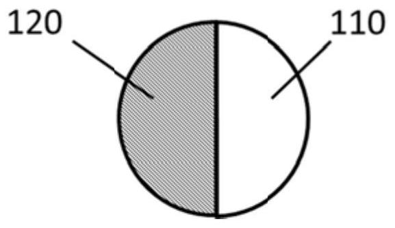
[0047] The structure of the micro-nanomotor is as follows figure 1 As shown, it includes a microsphere 110...

Embodiment 2

[0054] This embodiment provides a micro-nano motor, and the preparation process of the micro-nano motor is as follows:

[0055] (1) Take an appropriate amount of SiO with a diameter of 3 μm 2 Microsphere solution in a centrifuge tube, centrifuge;

[0056] (2) Add appropriate amount of ethanol and ultrasonically disperse to obtain SiO 2 ethanol dispersion;

[0057] (3) The dispersed SiO 2 The ethanol dispersion was spread flat on the glass slide, and after the ethanol volatilized, it was placed in a plasma sputtering apparatus for magnetron sputtering. The target material was Au, and the SiO 2 One side surface of the microsphere is sputtered to form an Au layer, the sputtering pressure is 2.0Pa, and the time is 5min;

[0058] (4) After the sputtering is completed, take out the glass slide and ultrasonically obtain the Au-SiO with Janus structure 2 micro-nanomotor.

[0059] The structure of the micro-nanomotor is as follows figure 1 As shown, it includes a microsphere 110...

Embodiment 3

[0066] This embodiment provides a micro-nano motor, and the preparation process of the micro-nano motor is as follows:

[0067] (1) Take an appropriate amount of SiO with a diameter of 5 μm 2 Microsphere solution in a centrifuge tube, centrifuge;

[0068] (2) Add appropriate amount of ethanol and ultrasonically disperse to obtain SiO 2 ethanol dispersion;

[0069] (3) The dispersed SiO 2 The ethanol dispersion was spread flat on the glass slide, and after the ethanol volatilized, it was placed in a plasma sputtering apparatus for magnetron sputtering. The target material was Au, and the SiO 2 One side surface of the microsphere is sputtered to form an Au layer, the sputtering pressure is 2.0Pa, and the time is 7min;

[0070] (4) After the sputtering is completed, take out the glass slide and ultrasonically obtain the Au-SiO with Janus structure 2 micro-nanomotor.

[0071] The structure of the micro-nanomotor is as follows figure 1 As shown, it includes a microsphere 110...


PUM


Abstract

The invention discloses a movement method of a micro-nano motor and a directional movement model of the micro-nano motor. The movement method of the micro-nano motor comprises the steps of dispersing the micro-nano motor in the main body liquid crystal; applying illumination to the micro-nano motor so as to enable the micro-nano motor to be subjected to self-thermophoresis in the main body liquid crystal; and applying voltage to the main body liquid crystal, changing the orientation of the main body liquid crystal, and then driving the micro-nano motor to directionally rotate in the movement direction. Illumination is applied to the micro-nano motor, so that the micro-nano motor generates self-thermophoresis. Under the condition, when the micro-nano motor moves in the main body liquid crystal to a position where the movement direction of the micro-nano motor needs to be changed, the orientation direction of the main body liquid crystal is changed through voltages on the two sides of the main body liquid crystal, and the movement direction of the micro-nano motor is deflected under the driving of rotation of the main body liquid crystal, so that the directional movement of the micro-nano motor under self-thermophoresis is controlled.

Description

technical field [0001] The present application relates to the technical field of micro-nano motors, in particular to a movement method of micro-nano motors and a directional motion model of micro-nano motors. Background technique [0002] Existing micro-nanomotors can be roughly divided into two categories, one is micro-nanomotors driven by fuel, and the other is micro-nanomotors driven by external stimuli. Fuel-driven micro-nano motors can generate energy to drive their own motion through the catalytic reaction of fuels such as hydrogen peroxide, hydrazine or organic dyes. The external field driving micro-nano can use ultrasound, magnetic field, heat, etc. as external stimuli to generate a driving force for the micro-nano motor. However, both of these two methods have the randomness of movement in the three-dimensional direction, that is, the directional movement of the micro-nano motor cannot be realized, which has greatly restricted the practical application of the micro...

Claims


Application Information

Patent Timeline
Patent Type & Authority Applications(China)
IPC IPC(8): H02N11/00B82Y15/00B82Y40/00
CPCH02N11/006B82Y15/00B82Y40/00
Inventor 胡小文李森董任峰周国富
Owner SOUTH CHINA NORMAL UNIVERSITY
Why Eureka
Try Eureka