Supercharge Your Innovation With Domain-Expert AI Agents!

Cutting device and sealing system

A cutting device and sealing box technology, applied in feeding devices, maintenance and safety accessories, manufacturing tools, etc., can solve the problems of internal pollution of the sealing box, complicated maintenance process, inconvenient replacement, etc., and achieve high operating stability, Easy disassembly and replacement, simple structure

Pending Publication Date: 2021-11-19
CHINA NUCLEAR POWER ENG CO LTD
View PDF8 Cites 0 Cited by
  • Summary
  • Abstract
  • Description
  • Claims
  • Application Information

AI Technical Summary

Problems solved by technology

In the prior art, the cutting device uses a grinding wheel to cut, which is easy to generate chips and cause internal pollution of the sealed box
[0003] In addition, the cutting device is fixed on the rotating mechanism, which is inconvenient to replace, and the power assembly of the rotating mechanism is placed inside the sealed box. Once the power assembly fails, the maintenance process is extremely complicated

Method used


Image

  • Cutting device and sealing system
  • Cutting device and sealing system
  • Cutting device and sealing system

Examples


Embodiment 1

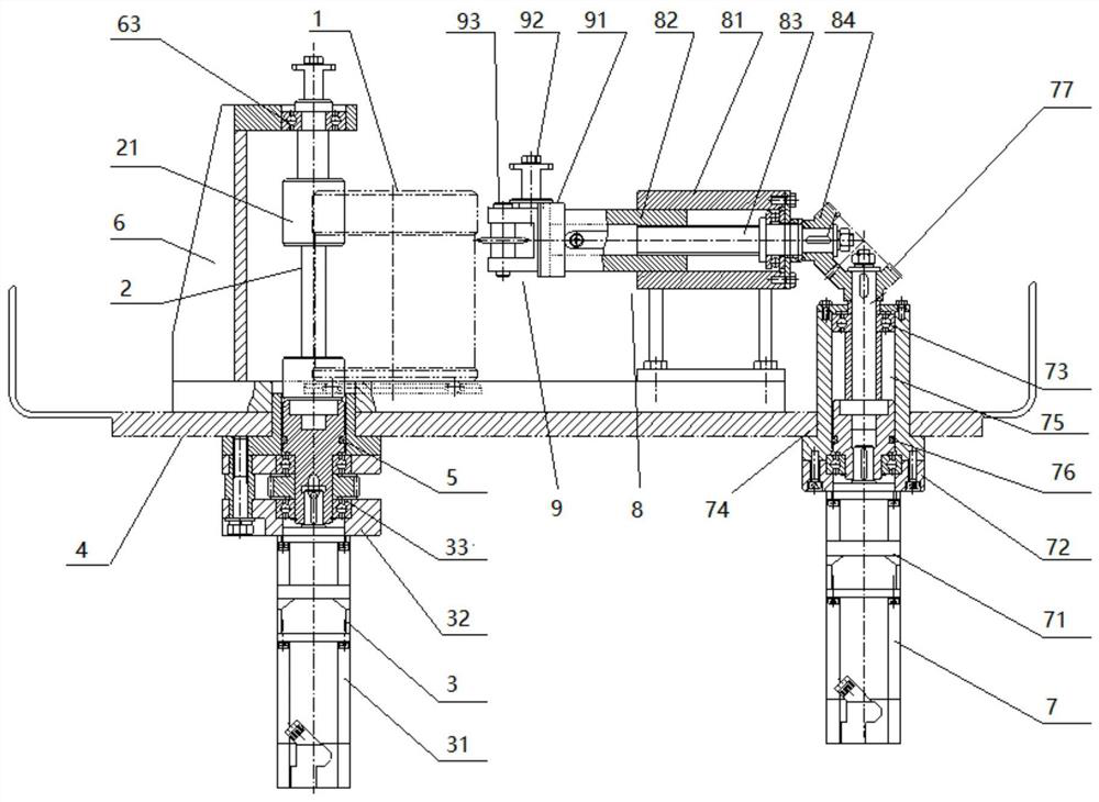
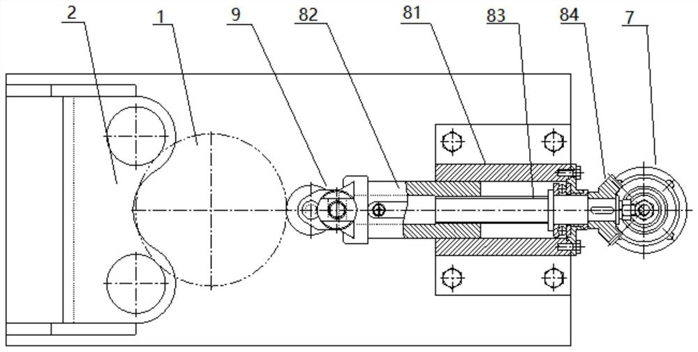
[0030] Such as figure 1 As shown, this embodiment discloses a cutting device, including a rotating mechanism, a feeding mechanism, and a cutting mechanism 9. The rotating mechanism includes a transmission support assembly and a rotary drive assembly 3. The rotary drive assembly 3 is arranged outside the sealed box 4 for Drive the transmission support assembly to rotate, the transmission support assembly is arranged in the sealed box 4, and is used to support the object 1 to be cut and drive the object 1 to be cut to rotate under the drive of the rotary drive assembly 3, and the cutting mechanism 9 is arranged in the sealed box 4 , for cutting the cut object 1, the feeding mechanism includes a feeding assembly 8 and a feeding drive assembly 7, the feeding assembly 8 is arranged in the sealed box 4, and is connected with the cutting mechanism 9, and is used to drive the cutting mechanism 9 moves toward the object to be cut 1, and the feed drive assembly 7 is arranged outside the...

Embodiment 2

[0044] This embodiment discloses a sealing system, which includes a sealing box 4, and a material cup is arranged inside the sealing box 4. The sealing system also includes the cutting device in Embodiment 1, and the cutting device is used to cut the material cup.

[0045] In this embodiment, the sealed box 4 has a good sealing performance, effectively blocking radiation-containing pollutants in the sealed box 4, and the cutting device can efficiently and stably complete the cutting of the material cup.

[0046] The working process of the sealing system is as follows:

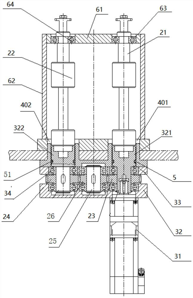
[0047] Place the cup on the first rotating shaft 21 and the second rotating shaft 22 inside the sealed box 4, turn on the first motor 31, and the first rotating shaft 21 and the second rotating shaft 22 rotate under the drive of the first motor 31 Thereby driving the material cup to rotate at a high speed.

[0048] Then, turn on the second motor 71, so that the first bevel gear 77 drives the second bevel gear ...


PUM


Abstract

The invention discloses a cutting device and a sealing system comprising the cutting device. The cutting device comprises a rotating mechanism, a feeding mechanism and a cutting mechanism, the rotating mechanism comprises a transmission supporting assembly and a rotation driving assembly, the rotation driving assembly is arranged outside a sealing box body and used for driving the transmission supporting assembly to rotate, the transmission supporting assembly is arranged in the sealing box body and used for supporting a cut object and driving the cut object to rotate under the driving of the rotation driving assembly, the cutting mechanism is arranged in the sealing box body and used for cutting the cut object, the feeding mechanism comprises a feeding assembly and a feeding driving assembly, the feeding assembly is arranged in the sealing box body, connected with the cutting mechanism and used for driving the cutting mechanism to move towards the cut object, and the feeding driving assembly is arranged outside the sealing box body, connected with the feeding assembly and used for providing power for the feeding assembly. The cutting device does not pollute the sealing box body during cutting.

Description

technical field [0001] The invention belongs to the technical field of nuclear industry, and in particular relates to a cutting device and a sealing system comprising the cutting device. Background technique [0002] In the field of nuclear industry, in order to prevent the spread of nuclear pollution, the cutting of the packaging material cup is generally carried out in a sealed box. In the prior art, the cutting device adopts a grinding wheel for cutting, which is easy to generate chips and cause internal pollution of the sealed box. [0003] In addition, the cutting device is fixed on the rotating mechanism, which is inconvenient to replace, and the power assembly of the rotating mechanism is placed inside the sealed box. Once the power assembly fails, the maintenance process is extremely complicated. [0004] Therefore, there is a need for a cutting device that does not pollute the sealed box. Contents of the invention [0005] The technical problem to be solved by t...

Claims


Application Information

Patent Timeline
IPC IPC(8): B23D79/00B23Q7/00B23Q5/22B23Q5/28B23Q11/08
CPCB23D79/00B23Q7/00B23Q5/22B23Q5/28B23Q11/08
Inventor 江保军杜军岭翟家海尚改彬
Owner CHINA NUCLEAR POWER ENG CO LTD
Features
  • R&D
  • Intellectual Property
  • Life Sciences
  • Materials
  • Tech Scout
  • Unparalleled Data Quality
  • Higher Quality Content
  • 60% Fewer Hallucinations
Learn More