Compression and expansion co-body machine for supercritical carbon dioxide Brayton system

A technology of carbon dioxide and compression expansion, which is applied in the direction of mechanical equipment, machines/engines, non-variable pumps, etc., can solve the problems of high cost, achieve the effects of reducing requirements, avoiding drive energy conversion, and improving rotor dynamics characteristics

Pending Publication Date: 2021-11-19
苏州欧拉透平机械有限公司
View PDF0 Cites 0 Cited by
  • Summary
  • Abstract
  • Description
  • Claims
  • Application Information

AI Technical Summary

Problems solved by technology

[0004] At the same time, the operating temperature of the expander is above 500°C, and the working pressure is above 20MPa. At present, there is no mechanical dynamic seal that meets the conditions. Even if a load-bearing mechanical dynamic seal is developed in the future, its cost will be huge. One of the technical difficulties in the study of supercritical carbon dioxide Brayton cycle

Method used


Image

  • Compression and expansion co-body machine for supercritical carbon dioxide Brayton system
  • Compression and expansion co-body machine for supercritical carbon dioxide Brayton system
  • Compression and expansion co-body machine for supercritical carbon dioxide Brayton system

Examples


Embodiment 1

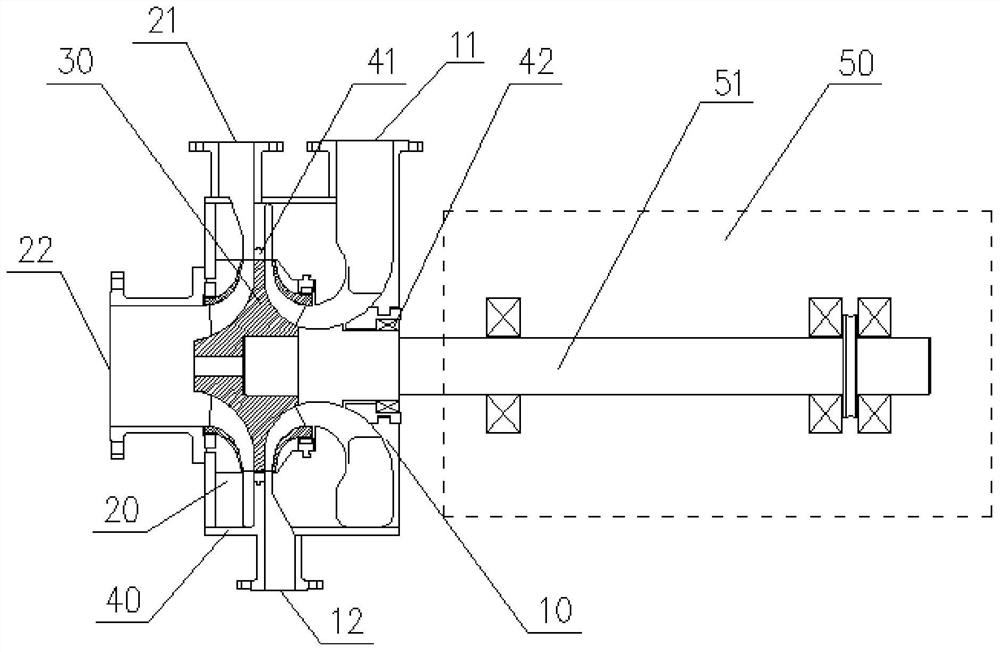
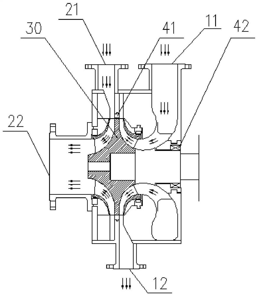
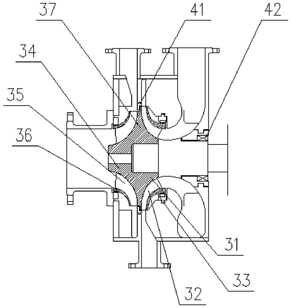
[0029] Embodiment 1: as Figure 1-3 As shown, the disk includes a compressor disk 31, an expander disk 34, and a middle disk 37, and the compressor disk 31 and the expander disk 34 are respectively located on both sides of the middle disk 37. The disk is an integral part, or at least one of the compressor disk 31 and the expander disk 34 is welded to the middle disk 37, and the mechanical gap seal 41 is radially or axially sleeved on the middle disk 37 . The compressor wheel 31, the compressor blade 32 and the compressor wheel cover 33 form a compressor impeller, and the compressor impeller is located in the compressor sealed chamber, the expander wheel 34, the expander blade 35 and the expander The wheel cover 36 forms the impeller of the expander, and the impeller of the expander is located in the sealed chamber of the expander. The impeller of the compressor and the impeller of the expander are arranged opposite to each other. As shown in Figure 1, the working medium of th...

Embodiment 2

[0030] Embodiment 2: as Figure 4 As shown, the disc includes a compressor disc 31, an expander disc 34 and a spacer 38, and the compressor disc 31 and the expander disc 34 are installed on both sides of the spacer 38 respectively, so The mechanical gap seal 41 is radially or axially sleeved on the spacer 38 . The compressor wheel 31 and the expander wheel 34 are processed separately, and then the two wheels are respectively installed on the spacer 38 to form an integral part. The spacer generally has a heat insulation function, and the compressor wheel 31 , the compressor blade 32 and the compressor wheel cover 33 form a compressor impeller, and the compressor impeller is located in the compressor seal cavity, and the expander wheel 34, the expander blade 35 and the expander wheel cover 36 form the expander impeller , and the expander impeller is located in the seal cavity of the expander, the compressor impeller and the expander impeller are arranged opposite to each other,...


PUM


Abstract

The invention relates to a compression and expansion co-body machine for a supercritical carbon dioxide Brayton system, which comprises a compressor and an expansion machine which are arranged in a cylinder body; the compressor and the expansion machine share a co-body impeller; the co-body impeller and the cylinder body form a compressor chamber and an expansion machine chamber which are mutually independent and closed; the compressor chamber is provided with a compressor air inlet end and a compressor air outlet end; the expansion machine chamber is provided with an expansion machine air inlet end and an expansion machine air outlet end; the co-body impeller is installed on a main shaft of a supporting unit; the compressor is located between the expansion machine and the supporting unit; one side of the compressor cavity and the expansion machine cavity are sealed through a mechanical gap sealing piece; and the other side of the compressor cavity and the external space are sealed through a mechanical dynamic sealing piece. A dynamic seal which is very difficult to design and is used for preventing high-temperature and high-pressure supercritical carbon dioxide gas of the expansion machine from leaking to an external space is omitted.

Description

technical field [0001] The invention relates to a Brayton system, in particular to a compression-expansion integrated machine for a supercritical carbon dioxide Brayton system. Background technique [0002] Due to the principle of no phase change, the Brayton cycle, as a source of energy and power, has a thermal efficiency much higher than about 40% of the current thermal power generation (Rankine cycle), and can theoretically reach more than 75%. Moreover, the required heat sources come from a wide range of sources, including fossil fuels, solar energy, biofuels, and even waste heat. The temperature range of the heat source is wide, and generally it can be used as long as it reaches above 500°C. High energy density, the same installed power, less and exquisite equipment. The required auxiliary conditions are less, such as the amount of cooling water is much smaller than that of thermal power plants, which is more environmentally friendly. For the supercritical carbon dio...

Claims


Application Information

Patent Timeline
Patent Type & Authority Applications(China)
IPC IPC(8): F04D25/04F01D15/08
Inventor 王鹏亮金仕熙金鼎铭
Owner 苏州欧拉透平机械有限公司
Why Eureka
Try Eureka