Flue gas purification system and cooling capacity comprehensive utilization process thereof
A flue gas purification system and flue gas technology, used in gas treatment, chemical instruments and methods, lighting and heating equipment, etc. Take advantage of the full effect
- Summary
- Abstract
- Description
- Claims
- Application Information
AI Technical Summary
Problems solved by technology
Method used
Image
Examples
Embodiment 1
[0052] A flue gas purification system includes a COAP system 1 and a carbon capture system 2 whose air inlet communicates with the exhaust port of the COAP system 1 . Among them, the COAP system 1 is used to desulfurize and denitrify the flue gas and then discharge it, and the carbon capture system 2 is used to remove carbon in the flue gas discharged from the COAP system 1 .
[0053] The present invention uses the COAP system and the carbon capture system in combination, not only can use the COAP process to remove SOx, NOx, Hg, HCl, HF, VOCs, etc. in the flue gas of the power plant; at the same time, combined with the carbon capture system, it can also The carbon in the flue gas can be removed, and the flue gas treated by the COAP system and the carbon capture system can achieve the goal of environmental protection and double carbon, and meet the needs of flue gas emptying.
[0054] The COAP system 1 in this embodiment may be a conventional COAP system, or a COAP system with ...
Embodiment 2
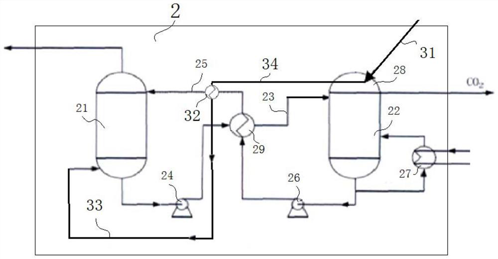
[0056] In this embodiment, the structure of a flue gas purification system is further optimized on the basis of Embodiment 1. In this embodiment, the carbon capture system 2 is a CO2 chemical absorption system, and a cooling capacity utilization pipeline system 3 is added at the same time. Effectively and rationally apply the cooling capacity in the low-temperature flue gas discharged from the COAP system 1, such as figure 2 As shown, the details are as follows:
[0057] The carbon capture system 2 includes an absorption tower 21 , a regeneration tower 22 , a rich liquid pipe 23 , a rich liquid pump 24 , a lean liquid pipe 25 , a lean liquid pump 26 , a reboiler 27 and a condenser 28 . Wherein, the absorption tower 21 has an air inlet, a gas outlet, a liquid inlet and a liquid outlet, and the regeneration tower 22 has a liquid inlet, a liquid outlet and an exhaust port; the bottom of the regeneration tower 22 is provided with a reboiler 27, and the top exhaust A condenser 28...
Embodiment 3
[0064] This embodiment further optimizes the structure of a flue gas purification system on the basis of embodiment 2. In this embodiment, a steam heat utilization pipeline system 4 is added, which can utilize steam of different qualities in the power plant step by step , to improve energy utilization, as follows:
[0065] The steam heat utilization pipeline system 4 includes a high-temperature steam delivery pipe 41 , a regeneration gas discharge pipe 42 , a steam recovery pipe 43 and a third heat exchanger 44 . Among them, the high-temperature steam delivery pipe 41 communicates with the regeneration gas inlet of the desulfurization adsorption tower 12 and / or the denitrification adsorption tower 14; the high-temperature steam discharged from the steam turbine of the power plant up to 300-350 ° C is used as the regeneration gas, and the regeneration gas is used as the regeneration gas The temperature of the regeneration gas after the desulfurization adsorption tower 12 and / or...
PUM
 Abstract
Description
Claims
Application Information
 - R&D
- Intellectual Property
- Life Sciences
- Materials
- Tech Scout
- Unparalleled Data Quality
- Higher Quality Content
- 60% Fewer Hallucinations
Browse by: Latest US Patents, China's latest patents, Technical Efficacy Thesaurus, Application Domain, Technology Topic, Popular Technical Reports.
© 2025 PatSnap. All rights reserved.Legal|Privacy policy|Modern Slavery Act Transparency Statement|Sitemap|About US| Contact US: help@patsnap.com


