Nitrification liquid bright backflow method

A technology of nitrifying liquid and return pipeline, which is applied in chemical instruments and methods, water/sludge/sewage treatment, biological water/sewage treatment, etc. Fluctuation and other problems can be achieved to ensure the denitrification efficiency, improve the wastewater treatment capacity, and improve the effect of backmixing.

Pending Publication Date: 2021-11-23
SHANDONG SHIHENG SPECIAL STEEL GROUP
View PDF6 Cites 0 Cited by
  • Summary
  • Abstract
  • Description
  • Claims
  • Application Information

AI Technical Summary

Problems solved by technology

Existing sewage treatment equipment has high energy consumption. The original design of biochemical treatment nitrification liquid backflow adopts dark backflow method. Poor back-mixing effect in the anoxic pool, insufficient wastewater treatment capacity, and fluctuations in effluent indicators

Method used


Image

  • Nitrification liquid bright backflow method
  • Nitrification liquid bright backflow method
  • Nitrification liquid bright backflow method

Examples


Embodiment 1

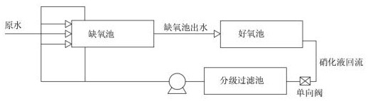
[0026] refer to image 3 As shown, the difference between this embodiment and other embodiments is that a graded filter tank is set under the aerobic tank, the graded filter tank is located between the nitrifying liquid pump and the aerobic tank, and multiple stages are connected to each other in the graded filter tank. The sedimentation chamber can be separated by partitions of different heights. The partitions are set from high to low from the liquid inlet to the liquid outlet, so as to play the role of graded sedimentation and ensure the nitrification in the lower sedimentation chamber. The impurity of the liquid is smaller than that of other sedimentation chambers, and the aerobic tank is connected with the graded filter tank through a pipeline, and the pipeline is used to lead out the nitrification liquid, and the nitrification liquid in the graded filter tank is supplied into the anoxic tank through the nitrification liquid pump;

[0027] The graded filter pool can filte...

Embodiment 2

[0029] refer to Figure 4 As shown, the difference between this embodiment and other embodiments is that a pneumatic pipeline is installed on the top of the anoxic tank, and the other end of the pneumatic pipeline is connected to a graded filter tank, and the gas in the anoxic tank can enter the graded filter through the pneumatic pipeline. pool;

[0030] When the sewage in the anoxic tank reacts, a large amount of gas will be produced. When the pressure reaches a certain level, the gas will be filled into the graded filter tank through the air pressure pipeline, which can increase the pressure in the graded filter tank, so that the nitrification hydraulic pressure in the graded filter tank can be reduced. Into the nitrifying liquid pump, reduce the working intensity of the nitrifying liquid pump, thereby further improving the service life of the nitrifying liquid pump, and can reduce energy consumption.

Embodiment 3

[0032] refer to Figure 5 As shown, the difference between this embodiment and other embodiments is that a quantitative tank is set between the anoxic tank and the nitrifying liquid pump, and the nitrifying liquid pump, the quantitative tank, and the aerobic tank are sequentially connected, and the quantitative tank acts as a Quantitative storage of nitrifying liquid;

[0033] Specifically, a float valve is installed in the quantitative tank, and a solenoid valve is installed on the pipeline connecting the anoxic tank and the quantitative tank. When the float valve reaches the limit liquid level, the solenoid valve will be opened, otherwise the solenoid valve will not be opened. , the float valve can be controlled by PLC. When the float valve reaches the limit liquid level, it means that the nitrifying liquid in the quantitative tank has reached the appropriate amount. At this time, the appropriate amount of nitrifying liquid in the quantitative tank can be sent to the anoxic ...


PUM


Abstract

A nitrification liquid bright backflow method comprises the following steps: (1) changing a backflow pipe from a concealed pipe to an exposed pipe; (2) feeding nitrification liquid in an aerobic tank into the front end of an anoxic tank by a nitrification liquid pump through an exposed pipe; and (3) calculating the required backflow quantity, and designing a water outlet at the tail end of the exposed pipe to ensure that outlet water is uniformly distributed and the water outlet quantity meets the requirement. The backflow pipe is changed from a concealed pipe to an exposed pipe, and the returned nitrification liquid enters from the front end of the anoxic tank, so that the back-mixing effect of high-concentration wastewater is improved, the denitrification efficiency of the anoxic tank is ensured, and the wastewater treatment capacity is improved.

Description

technical field [0001] The invention relates to the field of sewage treatment equipment, in particular to a method for reflux of nitrification liquid. Background technique [0002] At present, the sewage treatment process is to send the sewage into the anoxic tank first, then place the filler in the anoxic tank, and the sewage entering the anoxic tank will undergo preliminary degradation under the action of the filler, and pump the degraded sewage into the aerobic tank through the water pump. For re-degradation (ammonification reaction and nitrification reaction), the aerobic tank is equipped with fillers for degrading organic matter in the sewage, and the re-degraded sewage (containing nitrate) is pumped back to the anoxic tank through the reflux pump, and occurs in the anoxic tank. denitrification reaction. Existing sewage treatment equipment has high energy consumption. The original design of biochemical treatment nitrification liquid backflow adopts dark backflow method...

Claims


Application Information

Patent Timeline
IPC IPC(8): C02F3/30
CPCC02F3/305C02F3/303C02F2301/046
Inventor 吴东玉刘二场武文义马存亮丛干成王建同
Owner SHANDONG SHIHENG SPECIAL STEEL GROUP
Why Eureka
Try Eureka