SCR denitration device used for heat-engine plant

A thermal power plant and denitrification technology, applied in the field of flue gas denitrification, can solve the problems of failure of catalytic addition, unsatisfactory flue gas dust removal effect, decreased catalytic effect, etc., and achieves excellent dust removal effect, convenient denitration treatment, and rapid decline in effect. improved effect

Pending Publication Date: 2018-10-26
彭圆
View PDF8 Cites 4 Cited by
  • Summary
  • Abstract
  • Description
  • Claims
  • Application Information

AI Technical Summary

Problems solved by technology

[0005] However, on the one hand, this technical solution has an unsatisfactory dust removal effect on the flue gas, and the dust removal efficiency is low.

Method used


Image

  • SCR denitration device used for heat-engine plant
  • SCR denitration device used for heat-engine plant
  • SCR denitration device used for heat-engine plant

Examples


Example Embodiment

[0025] In order to make it easy to understand the technical means, creative features, goals and effects achieved by the present invention, the present invention will be further explained in conjunction with specific implementations below.

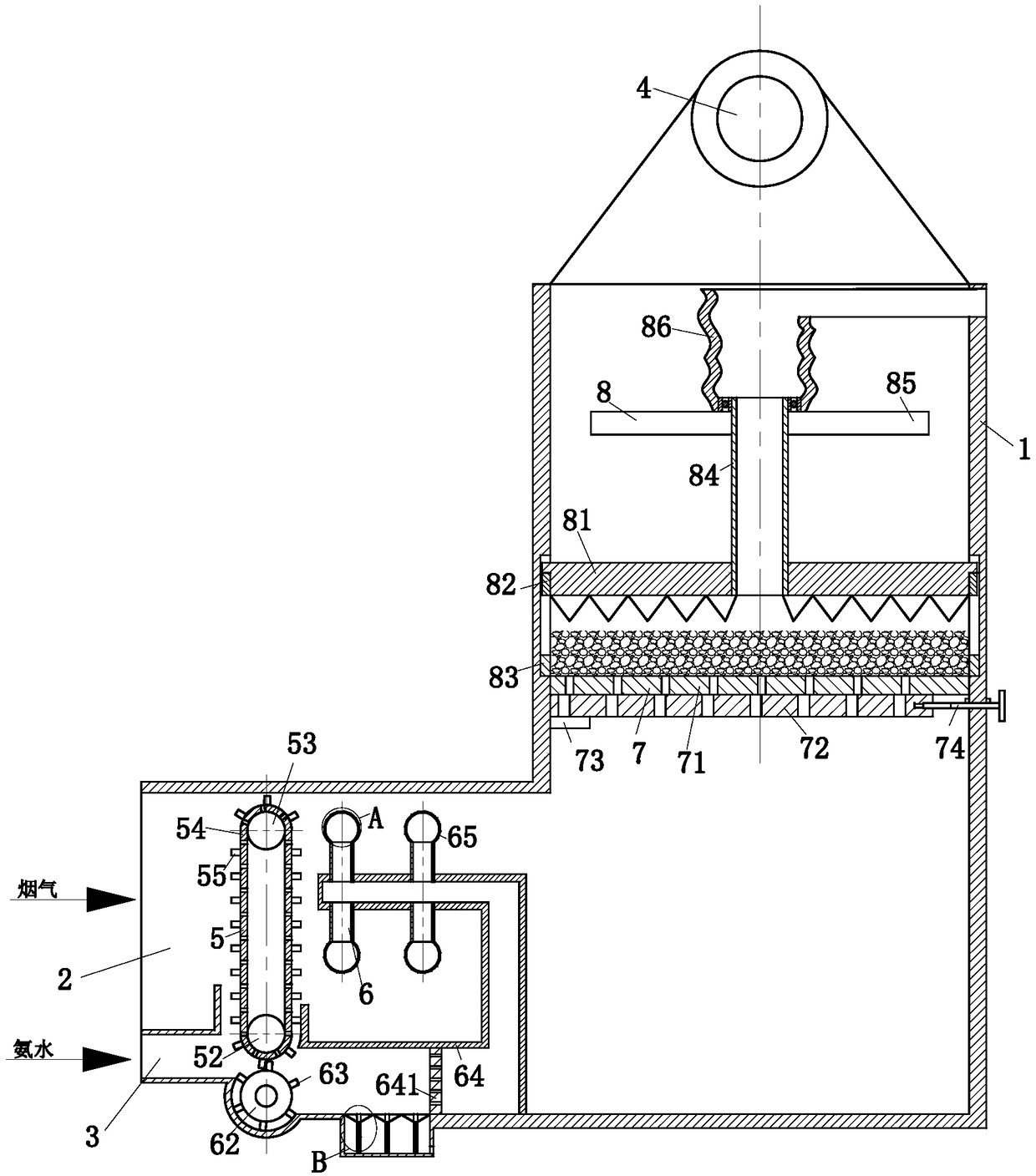
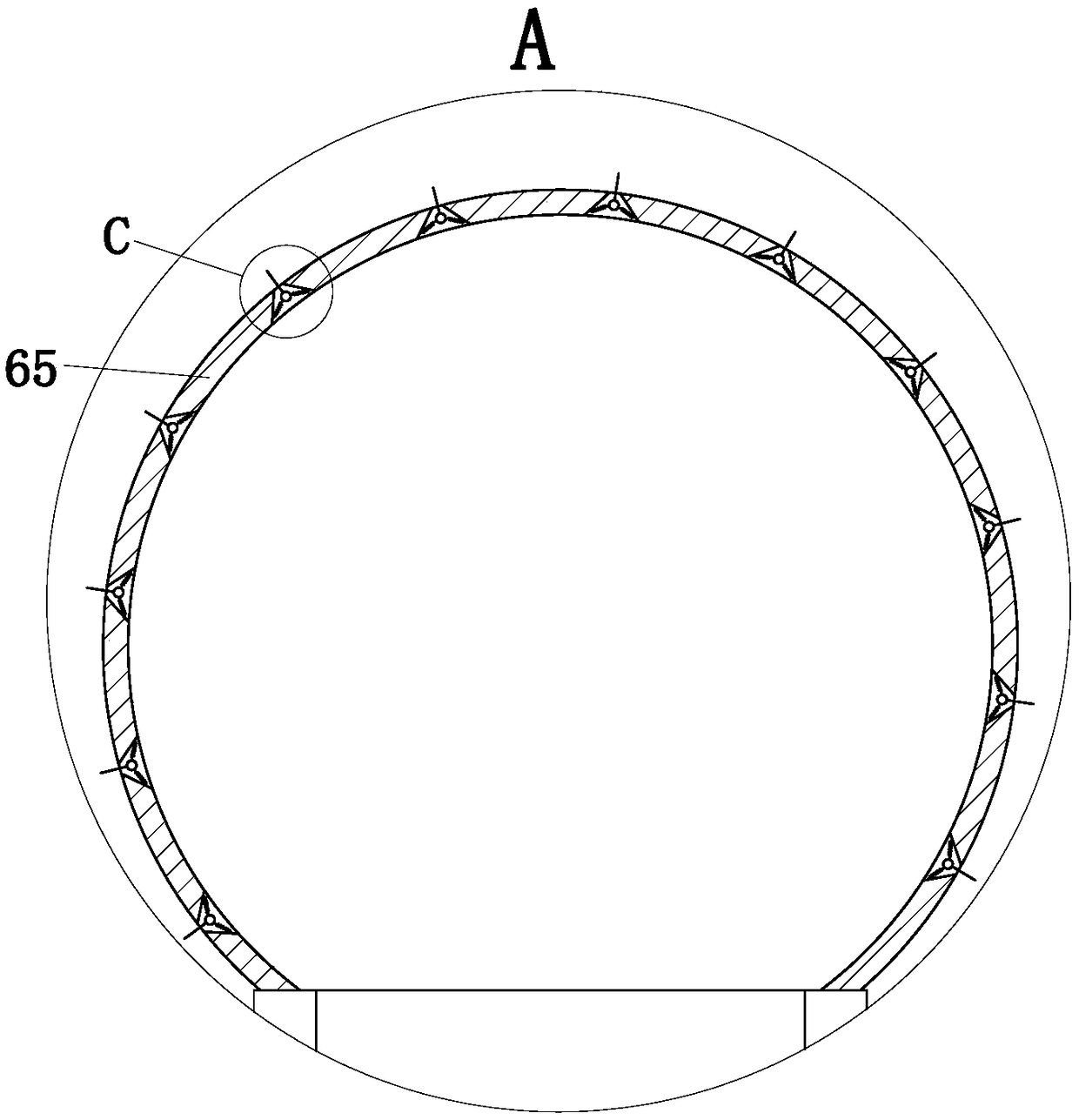
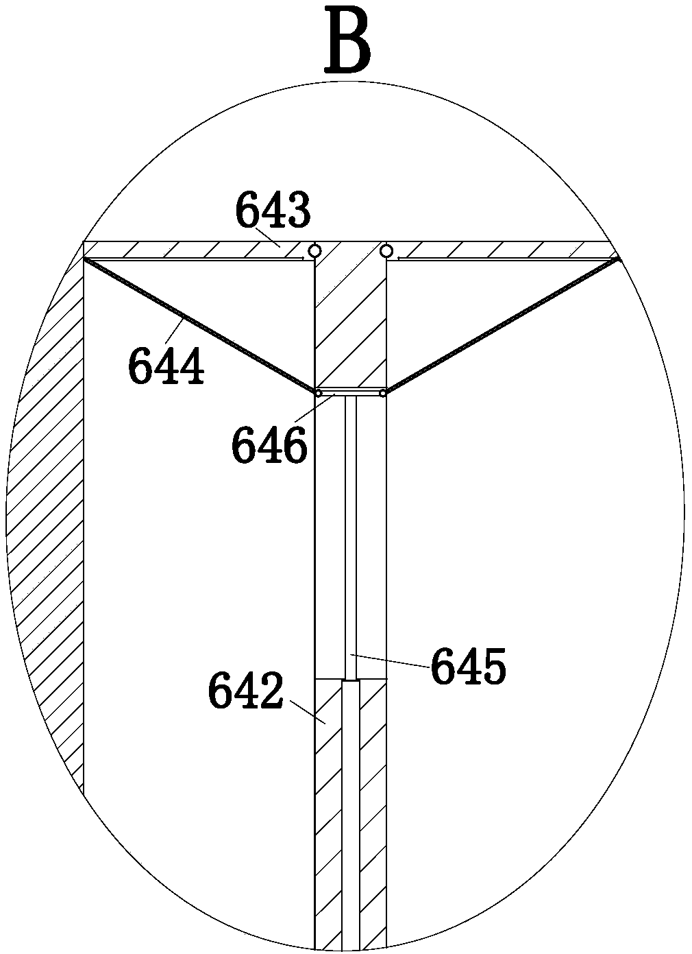
[0026] Such as Figure 1 to Figure 4 As shown, the SCR denitrification device for thermal power plants of the present invention includes a box body 1, a flue gas inlet 2, an ammonia water inlet pipe 3, a flue gas outlet 4, a dust removal module 5, an ammonia spray module 6, and a filter screen module 7. And the catalyst supplement module 8; the left side of the box 1 is provided with a flue gas inlet 2; the ammonia water inlet pipe 3 is located below the flue gas inlet 2; the top of the box 1 is provided with a flue gas outlet 4; The dust removal module 5 is located in the flue gas inlet 2. The dust removal module 5 is used to remove dust from the flue gas; the ammonia spray module 6 is installed on the ammonia inlet pipe 3, and the ammonia sp...


PUM


Abstract

The invention belongs to the technical field of flue gas denitration, and particularly relates to an SCR denitration device used for a heat-engine plant. The device comprises a box, a flue gas inlet,an ammonium hydroxide inlet pipe, a flue gas outlet, a dedusting module, an ammonium hydroxide spraying module, a filtering net module and a catalyst supplementing module; the flue gas inlet is formedin the left side of the box; the ammonium hydroxide inlet pipe is located under the flue gas inlet; the flue gas outlet is formed in the top of the box; the dedusting module is used for dedusting flue gas; the ammonium hydroxide spraying module is used for spraying ammonium hydroxide, and the ammonium hydroxide and the flue gas are mixed; the filtering net module is installed in the box; the catalyst supplementing module is located over the filtering net module, a annular groove is formed in the side wall of the box, and the catalyst supplementing module is installed in the annular groove ina sliding mode. The required flue gas denitration device is small in size and occupied space, a good flue gas dedusting effect and thorough dedusting are achieved, fast decline of the effect of a catalyst is relieved, a disabled portion on the surface layer of a catalyst is removed, and meanwhile, the catalyst is added freely.

Description

Technical field [0001] The invention belongs to the technical field of flue gas denitration, and specifically is an SCR denitration device for thermal power plants. Background technique [0002] Nitrogen oxides (NOx) in the flue gas of coal-fired power plants are one of the main air pollutants. At present, selective catalytic reduction technology (SCR) is mainly used to control the emission of nitrogen oxides in the flue gas, that is, the use of reducing agents is selective It reacts with the nitrogen oxides in the flue gas and generates non-toxic and pollution-free nitrogen (N 2 ) And water (H 2 O), to achieve the goal of denitration and environmental protection. [0003] At present, newly-built power plants usually adopt selective catalytic reduction (SCR) process for denitration. The SCR denitration system is generally composed of SCR reactor, catalyst module, ammonia storage and supply system, ammonia injection system, economizer bypass, SCR bypass and related test control sys...

Claims


Application Information

Patent Timeline
IPC IPC(8): B01D53/90B01D53/56B01D46/20B01D46/12
CPCB01D46/12B01D46/20B01D53/8631B01D53/90B01D2251/2062B01D2258/0283
Inventor 彭圆
Owner 彭圆
Why Eureka
Try Eureka