Universal waste heat exchanger

A heat exchanger, general-purpose technology, used in household heating, applications, heating fuels, etc., can solve the problem of low heating efficiency, and achieve the effect of maximizing heat exchange and achieving remarkable results.

Pending Publication Date: 2021-11-23
夏光超
View PDF0 Cites 0 Cited by
  • Summary
  • Abstract
  • Description
  • Claims
  • Application Information

AI Technical Summary

Problems solved by technology

Traditional waste heat utilization pots and stoves only focus on arranging water jackets or water rings in the area of ​​​​the smoke exhaust port, so as to perform "water-in-gas" heating, and the heating efficiency is often not high

Method used


Image

  • Universal waste heat exchanger
  • Universal waste heat exchanger
  • Universal waste heat exchanger

Examples


Embodiment Construction

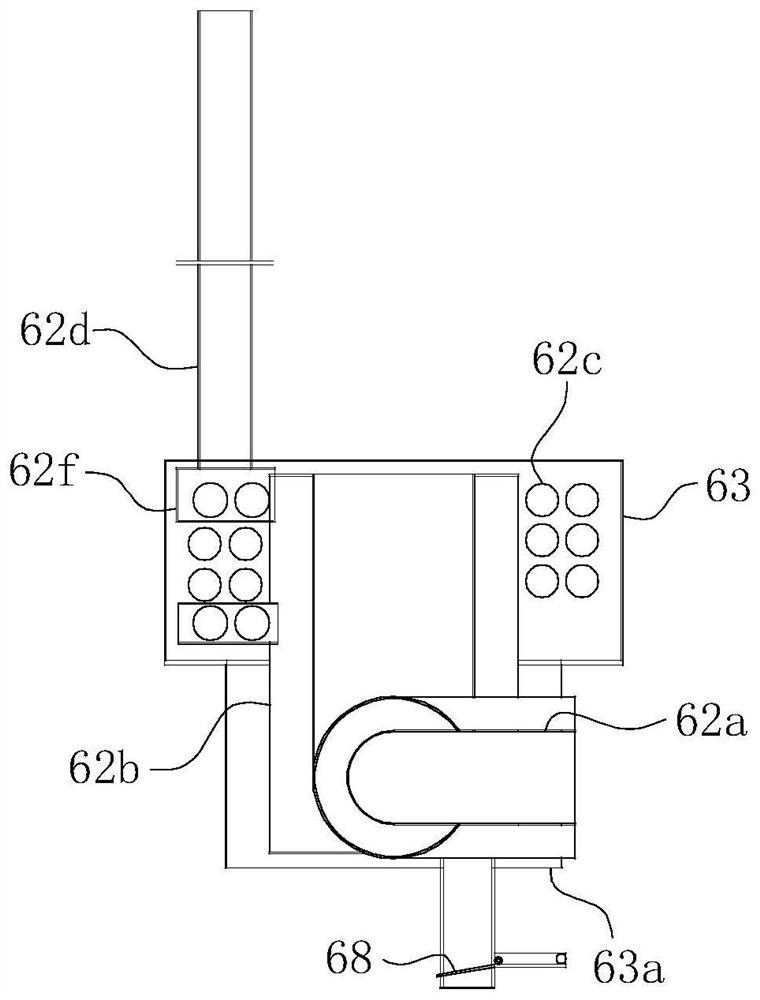
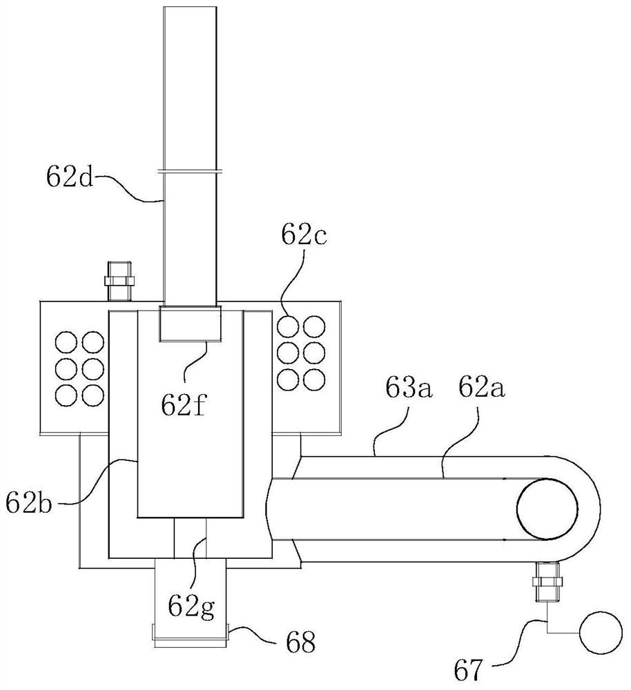
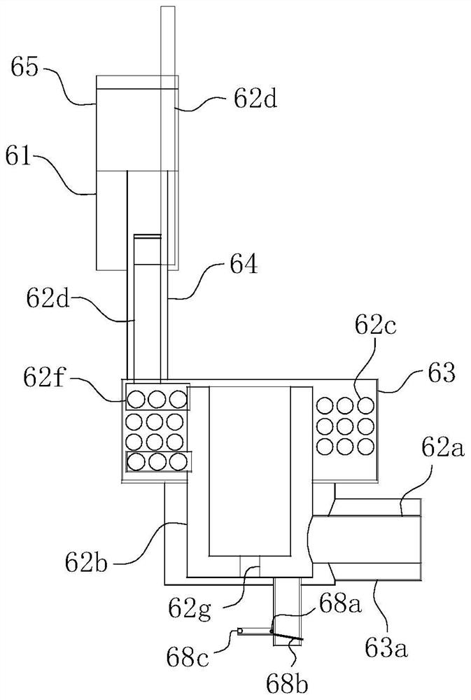
[0035] For ease of understanding, combined here Figure 1-5 , the concrete structure and working mode of the present invention are further described as follows:

[0036] The present invention depends on the difference of on-site application objects, such as Figure 1-2 The hot water type heat exchanger shown and the Figure 3-4 Two specific implementation classes of steam-type heat exchangers are shown. As the name implies, the hot water heat exchanger is used to realize the design function of turning waste heat into hot water, while the steam heat exchanger further realizes the design purpose of turning waste heat into steam. For the steam type heat exchanger, compared with the hot water type heat exchanger, such as steam discharge pipe 64, return water pipe 66 and even water vapor separation baffle 65a are added; because the structure is relatively more complicated, the steam Type heat exchanger is described as follows to the practical application structure of the present...


PUM


Abstract

The invention belongs to the technical field of cooking range waste heat utilization, and particularly relates to a universal waste heat exchanger. The universal waste heat exchanger comprises a heat exchange water tank, and an inlet pipe, a heat exchange sleeve, a heat exchange coil pipe and a waste gas discharge pipe which are sequentially arranged along a flue gas advancing path; the heat exchange sleeve is located in a cavity of the heat exchange water tank, and the inlet pipe penetrates through the heat exchange water tank and communicates with an inlet of the heat exchange sleeve; the heat exchange sleeve and the heat exchange coil pipe are coaxially arranged, and an outlet of the heat exchange sleeve communicates with an inlet of the heat exchange coil pipe; and an outlet of the heat exchange coil communicates with a waste gas exhaust pipe. While the normal heating requirement of the cooking range is met, the purpose of efficiently utilizing waste heat in the cooking range is achieved to the maximum extent.

Description

technical field [0001] The invention belongs to the technical field of stove waste heat utilization, and in particular relates to a general-purpose waste heat heat exchanger. Background technique [0002] There are many specific structural shapes of stoves, which are mainly reflected in the differences in gas appliances. The purpose is to improve the utilization rate of gas and improve work efficiency. Because the combustion flame of the stove is very strong, the exhaust gas produced by the combustion is very high in temperature. The high-temperature flue gas generated by the ordinary stove will be directly discharged from the smoke exhaust port of the stove hearth, which not only wastes heat energy, but also causes the working environment of the stove to be very bad. . Later, one after another, some people began to add waste heat utilization equipment to the stove, most of which were crude and installed water-cooled coils at the smoke exhaust port of the furnace, so as to ...

Claims


Application Information

Patent Timeline
IPC IPC(8): F24C13/00F24C3/12
CPCF24C13/00F24C3/12
Inventor 夏光超
Owner 夏光超
Why Eureka
Try Eureka