
Novel stator structure based on axial flux motor

A technology of axial magnetic flux and stator structure, applied in the shape/pattern/structure of magnetic circuit, shape/pattern/structure of winding insulation, shape/pattern/structure of winding conductor, etc. Problems such as difficult processing and assembly, to achieve good mechanical strength and heat dissipation characteristics, low cost, and improve work efficiency

Active Publication Date: 2021-11-23
HUBEI UNIV OF TECH
View PDF5 Cites 0 Cited by
  • Summary
  • Abstract
  • Description
  • Claims
  • Application Information

AI Technical Summary

Problems solved by technology

Therefore, most permanent magnet synchronous motor windings will affect the performance of the motor due to the saturation of the magnetic circuit
In recent years, the permanent magnets of motors designed to improve the sinusoidal nature of the motor air gap magnetic density adopt the Halbach array arrangement, but this arrangement not only needs to consider the size of the permanent magnet block, the manufacturability of magnetization and installation, but also the permanent magnets. Magnets are difficult to process and assemble

Method used


Image

  • Novel stator structure based on axial flux motor
  • Novel stator structure based on axial flux motor
  • Novel stator structure based on axial flux motor

Examples


Embodiment 1

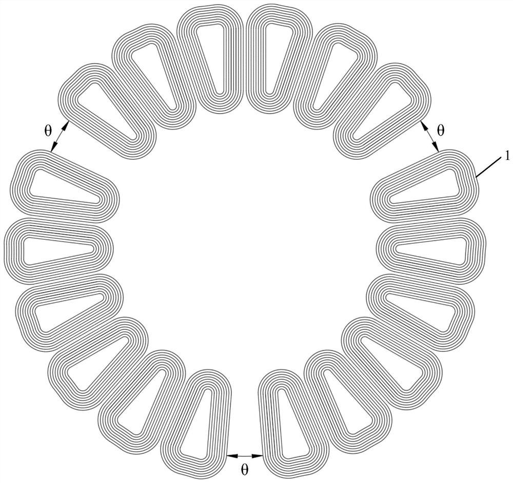
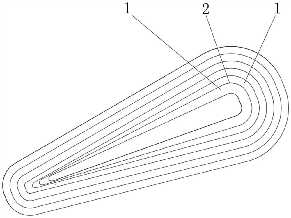
[0023] refer to Figure 1-Figure 2 , this embodiment discloses a new stator structure based on an axial flux motor, which includes more than three coil monomers of the same specification distributed in the stator in a ring. Taking a three-phase motor as an example, the coil monomers in this embodiment It is the coil monomer inside the axial ironless motor, that is, the material of the stator core 3 is air, and the coil monomer is wound by a plurality of enameled wires 1, and there is an insulating material 2 between two adjacent enameled wires 1, and the insulating material 2 Form inter-turn insulation, separate the conductors with different potentials in the motor winding from each other, so as to avoid inter-turn short circuit, each adjacent N coil monomers form a coil unit, and there are three coil units in the stator. The included angle between two adjacent coil units is θ, and the value range of θ is 2-35 degrees. The coil monomers in each coil unit are uniformly distribu...

Embodiment 2

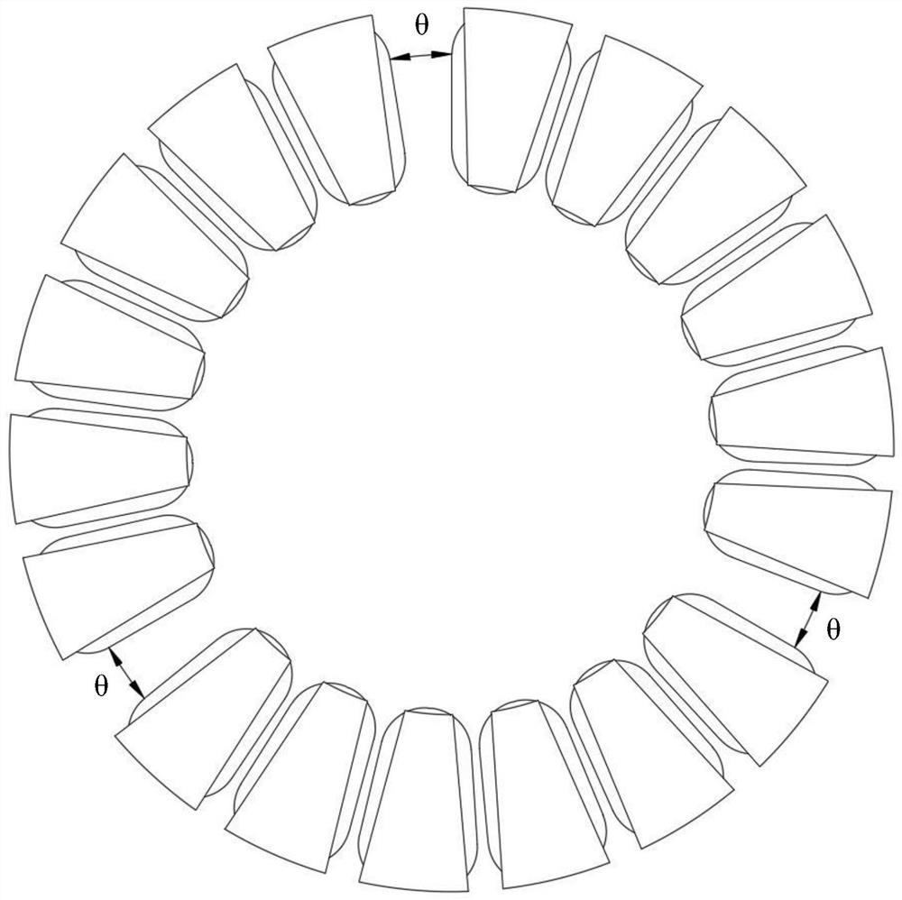
[0025] refer to Figure 3-Figure 4 , this embodiment discloses a new stator structure based on an axial flux motor, which includes more than three coil monomers of the same specification distributed in the stator in a ring. Taking a three-phase motor as an example, the coil monomers in this embodiment It is a single coil inside the axial iron core motor, which is composed of a stator core 3 and a winding 4 wound on the stator core 3. The material of the stator core 3 is selected from one of iron, magnetic powder core and soft magnetic composite material. The winding 4 is made of enameled wire 1 with an insulating layer; the stator core 3 and the winding 4 are separated by insulating paper or insulating varnish to avoid electrical connection between the winding 4 and the stator core 3 . The coil monomers that make up the stator are arranged in a ring-shaped and non-uniform manner. Every adjacent N coil monomers form a coil unit. There are three coil units in the stator. The ang...


PUM


Abstract

The invention discloses a novel stator structure of an axial magnetic flux motor, which comprises more than three coil monomers which are annularly distributed in a stator and have the same specification, every N adjacent coil monomers form a coil unit, three coil units are arranged in the stator, the included angle between any two adjacent coil units is theta, and theta is greater than or equal to 1. The value range of theta is 2-35 degrees, and the coil monomers in each coil unit are annularly and uniformly distributed in an array at the angle of 360-3*theta. The invention provides a non-uniformly distributed stator structure of an axial magnetic flux motor, which is simultaneously suitable for an axial magnetic flux motor with an iron core and an axial magnetic flux motor without an iron core, can effectively reduce higher harmonics of counter electromotive force of the motor, and improves the sinusoidal property of the output voltage waveform of the motor.

Description

technical field [0001] The invention relates to the technical field of motors, in particular to a novel stator structure of an axial flux motor. Background technique [0002] In traditional permanent magnet synchronous motors, in order to improve the utilization rate of effective space windings, the windings are always designed to be evenly distributed. Therefore, most permanent magnet synchronous motor windings will affect the performance of the motor due to the saturation of the magnetic circuit. In recent years, the permanent magnets of motors designed to improve the sinusoidal nature of the motor air gap flux density adopt the Halbach array arrangement, but this arrangement not only needs to consider the size of the permanent magnet block, the manufacturability of magnetization and installation, but also the permanent magnets. Magnets are difficult to process and assemble. Although it is proposed in the prior art to change the distribution of the stator windings to imp...

Claims


Application Information

Patent Timeline
Patent Type & Authority Applications(China)
IPC IPC(8): H02K1/12H02K3/28H02K3/34H02K3/38
CPCH02K1/12H02K3/28H02K3/345H02K3/38H02K2213/03H02K2201/12
Inventor 王晓光李晓凤
Owner HUBEI UNIV OF TECH
Learn More