
Abrasive polishing equipment

A kind of equipment and abrasive technology, applied in the field of abrasive polishing equipment, can solve the problems of reduced polishing efficiency, long recovery path, and reduced processing efficiency, and achieve high polishing efficiency

Inactive Publication Date: 2021-11-26
杭州奔涌机械有限公司
View PDF11 Cites 0 Cited by
  • Summary
  • Abstract
  • Description
  • Claims
  • Application Information

AI Technical Summary

Problems solved by technology

[0005] (1) The abrasive recovery needs to go back to the storage cavity through the transport mechanism and the recovery mechanism. The recovery path of the abrasive is very long, and it needs to go through multiple horizontal and vertical path transfers in the process, resulting in extremely low efficiency of abrasive recovery and a huge Reduced polishing efficiency
[0006] (2) When the abrasive is recycled into the storage chamber, the storage chamber is in an open state, the polishing process must be suspended, and the pressure can be continued only after the storage chamber is closed again, otherwise the abrasive will be squeezed and leaked out, so the processing efficiency will be reduced
[0007] (3) After the workpiece is processed, abrasives will remain in the inner cavity of the workpiece, which is very inconvenient to clean

Method used


Image

  • Abrasive polishing equipment
  • Abrasive polishing equipment
  • Abrasive polishing equipment

Examples


Embodiment Construction

[0043] The present invention will be described in detail below, and the technical solutions in the embodiments of the present invention will be clearly and completely described. Apparently, the described embodiments are only some of the embodiments of the present invention, not all of them. Based on the embodiments of the present invention, all other embodiments obtained by persons of ordinary skill in the art without making creative efforts belong to the protection scope of the present invention.

[0044] The present invention provides a kind of abrasive polishing equipment here by improving, and technical scheme of the present invention is:

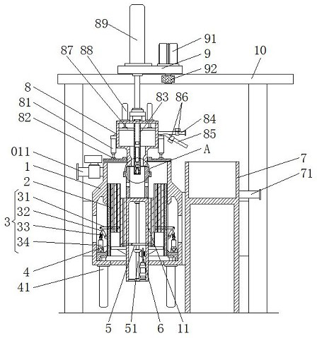
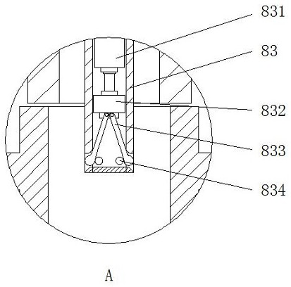
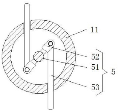
[0045] Such as Figure 1-Figure 12 As shown, a kind of abrasive polishing equipment comprises a bottom cylinder 1, the center of the bottom cylinder 1 is provided with a lower support platform 11, and the height of the top opening of the bottom cylinder 1 is greater than the top height of the lower support platform 11, the bottom cylind...


PUM


Abstract

The invention relates to the technical field of polishing equipment, in particular to abrasive polishing equipment which comprises a bottom cylinder barrel. A lower supporting table is arranged in the center of the bottom cylinder barrel, the height of a top opening of the bottom cylinder barrel is larger than the height of the top of the lower supporting table, an active push-pull barrel is slidably connected to the inner wall of the bottom cylinder barrel, a plurality of passive adjusting barrels which are connected in a sleeving mode are arranged between the inner wall of the active push-pull barrel and the outer wall of the lower supporting table, and the active push-pull barrel and the lower supporting table are connected with the passive adjusting barrels in a matched mode through a joint adjusting mechanism and a limiting adjusting assembly. According to the abrasive polishing equipment provided by the invention, through the mutual cooperation of the bottom cylinder barrel, the active push-pull barrel, the passive adjusting barrels and an upper pressing table, an abrasive can be directly extruded again to flow back into a workpiece after being extruded out of the workpiece, polishing is achieved by enabling the abrasive to continuously flow inside and outside the workpiece, the abrasive does not need to be recycled after passing through complex transverse and longitudinal moving paths in the process, and the polishing efficiency is higher by directly utilizing the mode that the abrasive flows inside and outside the workpiece in a reciprocating mode.

Description

technical field [0001] The invention relates to the technical field of polishing equipment, in particular to abrasive polishing equipment. Background technique [0002] Polishing refers to the use of mechanical, chemical or electrochemical action to reduce the surface roughness of the workpiece to obtain a bright and smooth surface. It is a modification process on the surface of the workpiece by using polishing tools and abrasive particles or other polishing media. [0003] Chinese Invention Patent Publication No. CN112338786A discloses an abrasive flow polishing device capable of recovering abrasives for repeated use. The invention discloses an abrasive flow polishing device capable of recovering abrasives for repeated use, including a fixed body, and the right part of the fixed body is fixedly installed There is a conveying body, the right side of the conveying body is slidingly installed with a recycling body, and an extruding body is fixedly installed above the recyclin...

Claims


Application Information

Patent Timeline
IPC IPC(8): B24B31/10B24B31/12B24B31/14
CPCB24B31/10B24B31/12B24B31/14
Inventor 王敏
Owner 杭州奔涌机械有限公司
Learn More