
Power supply vehicle for supplying power to outside and working method

A power supply vehicle and electric technology, which is applied to electric vehicles, load supply circuits, battery circuit devices, etc., can solve problems such as restricting the reaction speed and combat effectiveness of radar vehicles, increasing the deployment and withdrawal time of power supply vehicles, and inconvenient personnel operations. , to achieve the effect of convenient operation and maintenance, compact structure and good heat dissipation

Pending Publication Date: 2021-11-26
SHANGHAI INST OF ELECTROMECHANICAL ENG
View PDF11 Cites 0 Cited by
  • Summary
  • Abstract
  • Description
  • Claims
  • Application Information

AI Technical Summary

Problems solved by technology

The cables suitable for high-power power supply are relatively thick, and it is inconvenient for personnel to operate, which greatly increases the deployment and withdrawal time of the power supply vehicle, and restricts the response speed and combat effectiveness of the radar vehicle

Method used


Image

  • Power supply vehicle for supplying power to outside and working method
  • Power supply vehicle for supplying power to outside and working method
  • Power supply vehicle for supplying power to outside and working method

Examples


Embodiment 1

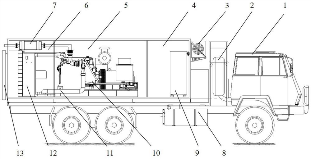
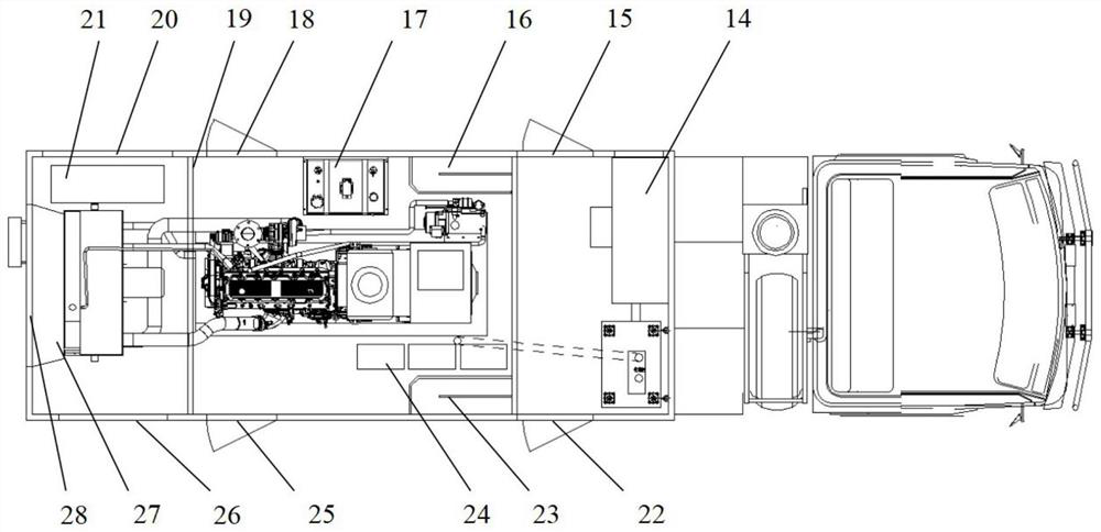
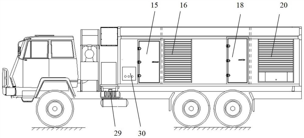
[0072] Such as Figure 1 to Figure 3 Shown, a kind of power source vehicle of external power supply, comprises: vehicle chassis, unit system, compartment and electric cable reel 14; The unit system includes: smoke exhaust pipe 7, control cabinet 9, generator-engine combination 10, radiator 12 and battery pack 24; smoke exhaust pipe 7 and radiator 12 are connected to generator-engine combination 10, and control cabinet 9 is connected to generator-engine combination 10 and battery pack 24. Car chassis includes: car body 1, spare tire 2, chassis oil tank 8 and chassis battery 29; The chassis fuel tank 8 and the chassis battery 29 are installed on the side, and the electric cable reel 14 is electrically connected to the chassis battery 29 and the generator-engine combination 10; the unit system also includes: a fuel tank 17 and a resistance load 21; the control cabinet 9 is electrically connected to the fuel tank 17 and the resistance load 21. The generator-engine combination 10...

Embodiment 2

[0079] Embodiment 2 is a preferred example of Embodiment 1.

[0080] A high-power power supply car capable of rapidly supplying external power includes: a car chassis, a unit system, a cabin and an electric cable reel 14 . The chassis includes: car body 1, chassis battery 29, chassis fuel tank 8 and spare tire 2; the unit system includes: control cabinet 9, generator engine combination 10, fuel tank 17, radiator 12, smoke exhaust pipe 7, and resistance load 21 And battery pack 24; The compartment is divided into front cabin 4, middle cabin 5 and rear cabin 6 three parts.

[0081] The control cabinet 9 and the electric cable reel 14 are installed in the front cabin 4, the air conditioner 3 is installed on the front wall of the front cabin 4, the first single door 15 and the third single door 22 are arranged on both sides of the front cabin, and the generator engine combination is installed in the middle cabin 5 10. The battery pack 24 and the fuel tank 17, the first air inlet ...


PUM


Abstract

The invention provides a power supply vehicle for supplying power to outside and a working method. The power supply vehicle comprises a chassis, a unit system, a compartment and an electric cable reel, the compartment is installed on the chassis, and the unit system and the electric cable reel are installed in the compartment. The unit system comprises a smoke exhaust pipe, a control cabinet, a generator and engine combination, a radiator and a storage battery pack. The smoke exhaust pipe and the radiator are connected with the generator and engine combination, and the control cabinet is connected with the generator and engine combination and the storage battery pack. The unit system adopts a split type design, and the compartment adopts a compartment type design, so that the heat dissipation performance of the whole vehicle is good, and the assembly, disassembly and maintenance are convenient.

Description

technical field [0001] The invention relates to the field of mobile power supply equipment, in particular to a power supply vehicle for external power supply and a working method. Background technique [0002] The power supply vehicle involved in the present invention provides working power for a radar vehicle. During the deployment of the radar vehicle, the power supply vehicle stops at a distance of tens of meters beside the radar vehicle, connects the power supply cable, and starts the power supply vehicle to supply power to the radar vehicle. With the development of radar technology, the power of radar is getting bigger and bigger, and the power demand for power supply vehicles is also increasing. The design of the high-power power supply vehicle should ensure the heat dissipation of the power station unit. At the same time, the deployment speed of the power supply vehicle is an important link that restricts the response speed and combat effectiveness of the radar vehicl...

Claims


Application Information

Patent Timeline
IPC IPC(8): B60P3/00H02J7/00
CPCB60P3/00H02J7/0063H02J7/14
Inventor 缪东辉朱峰赵起超洪林程志马张健王惠娟彭永红刘可平李萧萧
Owner SHANGHAI INST OF ELECTROMECHANICAL ENG
Learn More