
Fan-shaped cast-in-place hollow floor type storage tank leveling foundation and construction method thereof

A technology for storage tank foundations and hollow floors, which can be applied to foundation structure engineering, protection devices, buildings, etc., and can solve the problems of difficulty in satisfying the characteristic value of the horizontal bearing capacity of single piles, increased project investment, and large horizontal seismic forces of storage tank foundations. problems, to achieve the effect of saving construction procedures, simplifying construction procedures and reducing earthquake response

Active Publication Date: 2021-11-26
浙江省天正设计工程有限公司
View PDF6 Cites 1 Cited by
  • Summary
  • Abstract
  • Description
  • Claims
  • Application Information

AI Technical Summary

Problems solved by technology

In areas of weak foundation soil with high seismic intensity, the horizontal seismic force on the foundation of the storage tank is relatively large. In such projects, the characteristic value of the vertical bearing capacity of a single pile is often easier to satisfy, while the characteristic value of the horizontal bearing capacity of a single pile is not easy to satisfy.
When the number of piles is controlled by the characteristic value of the horizontal bearing capacity, the project investment increases

Method used


Image

  • Fan-shaped cast-in-place hollow floor type storage tank leveling foundation and construction method thereof
  • Fan-shaped cast-in-place hollow floor type storage tank leveling foundation and construction method thereof
  • Fan-shaped cast-in-place hollow floor type storage tank leveling foundation and construction method thereof

Examples


Embodiment Construction

[0039] The present invention will be further described below in conjunction with the accompanying drawings of the description.

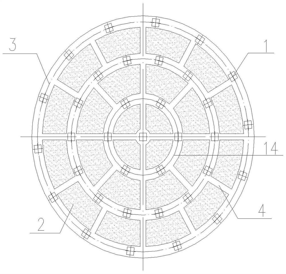
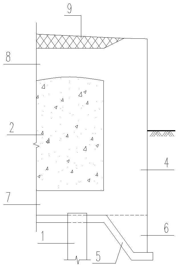
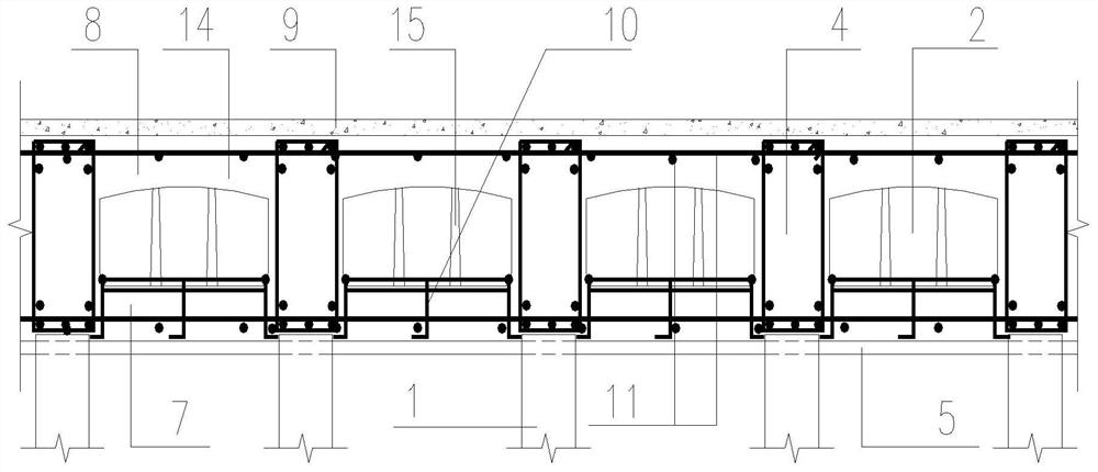
[0040] Such as Figure 1-2 As shown, a fan-shaped arrangement of cast-in-situ hollow floor storage tank leveling foundation, including storage tank foundation pile foundation 1, storage tank foundation plain concrete cushion 5, fan-shaped arrangement of cast-in-situ hollow floor storage tank leveling The foundation 14 and the asphalt sand cushion 9 are composed of the cast-in-place hollow floor storage tank leveling foundation 14 arranged in a fan shape as a toe-type foundation raft, and the plain concrete cushion 5 of the storage tank foundation is set on the pile foundation 1 and the foundation storage tank foundation. Between the fan-shaped cast-in-place hollow floor storage tank leveling foundations 14, the asphalt sand cushion layer 9 is arranged on the fan-shaped cast-in-place hollow floor storage tank leveling foundations 14.

[0041] Among t...


PUM


Abstract

The invention discloses a fan-shaped cast-in-place hollow floor type storage tank leveling foundation and a construction method thereof, and belongs to the technical field of chemical storage. The fan-shaped cast-in-place hollow floor type storage tank leveling foundation comprises a foundation pile foundation, a foundation plain concrete cushion layer, an asphaltic sand cushion layer and a cast-in-place hollow floor type storage tank foundation arranged between the foundation plain concrete cushion layer and the asphaltic sand cushion layer. The cast-in-place hollow floor type storage tank foundation is formed by integrally pouring fan-shaped foam concrete solid blocks and reinforced concrete beams arranged in the annular direction and the normal direction. The fan-shaped foam concrete solid blocks are connected through a base formed by welding reinforcing steel bars and cross binding of the base and anchor bars at the top of a pile foundation, so that accurate construction positioning of the foam concrete solid blocks is achieved, and meanwhile the problem that the foam concrete solid blocks float upwards when storage tank foundation concrete is poured and tamped is solved. The storage tank foundation concrete can be poured and tamped in place at a time. A concrete toe is arranged on the lower side of the periphery of the cast-in-place hollow floor type storage tank foundation, and the horizontal earthquake resisting bearing capacity of the storage tank foundation is improved.

Description

technical field [0001] The invention relates to the technical field of chemical product storage, in particular to a fan-shaped cast-in-place hollow floor storage tank leveling foundation and a construction method thereof. Background technique [0002] The traditional storage tank foundation structure generally includes 100 thick plain concrete cushion, cast-in-place reinforced concrete solid storage tank foundation, medium and coarse sand cushion, and asphalt sand cushion from bottom to top. Among them, the main function of the medium and coarse sand cushion is to adjust the uneven settlement of the tank foundation. However, through the leveling design of the foundation pile foundation, the uneven settlement of the storage tank foundation can be controlled within the range specified by the code, so the effect of the medium and coarse sand cushion is not obvious. Moreover, the construction of medium and coarse sand cushions is relatively difficult. When using construction ma...

Claims


Application Information

Patent Timeline
Patent Type & Authority Applications(China)
IPC IPC(8): E02D27/38E02D35/00E02D31/08E02D27/12E02D15/02
CPCE02D27/38E02D35/00E02D31/08E02D27/12E02D15/02
Inventor 张瑞松朱翔梁双双
Owner 浙江省天正设计工程有限公司
Learn More