Method for demodulating quadrature phase shift keying modulation signal

A quadrature phase shift keying and modulation signal technology, applied in the field of signal processing, can solve the problems of amplitude quantization error, affecting the receiving sensitivity and dynamic range of the transponder, long settling time, etc., to reduce the amplitude quantization error and phase truncation error, improvement of receiving sensitivity and dynamic range, and excellent effect of phase orthogonality

Pending Publication Date: 2021-11-26
SHAANXI CHANGLING ELECTRONICS TECH
View PDF0 Cites 1 Cited by
  • Summary
  • Abstract
  • Description
  • Claims
  • Application Information

AI Technical Summary

Problems solved by technology

[0007] Because the automatic frequency control AFC of this method generally adopts the method of cross-product AFC or frequency sweep, the frequency acquisition time is more than milliseconds, and the phase tracking adopts the Costas loop. The Costas loop includes a phase-locked loop and belongs to a negative feedback loop to achieve carrier synchronization. It also takes a long time to set up, and the transient noise is likely to cause the phase-locked loop to lose lock. After the lock is lost, frequency acquisition and phase tracking need to be re-performed to achieve carrier synchronization again.
[0008] 2. There are phase truncation errors and amplitude quantization errors, which affect the receiving sensitivity and dynamic range of the transponder
[0019] 4. Occupies more circuit hardware resources

Method used


Image

  • Method for demodulating quadrature phase shift keying modulation signal
  • Method for demodulating quadrature phase shift keying modulation signal
  • Method for demodulating quadrature phase shift keying modulation signal

Examples


Embodiment Construction

[0071] Embodiments of the present invention will be described in detail below in conjunction with the accompanying drawings.

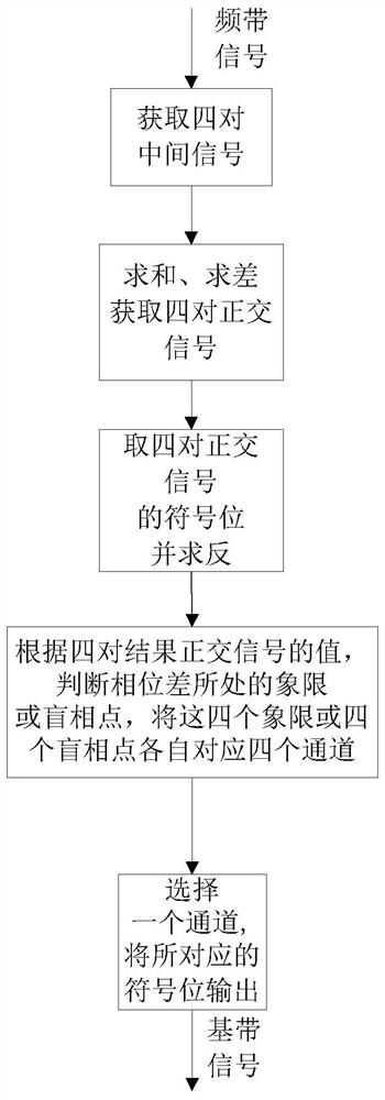
[0072] refer to figure 1 , the demodulation method of quadrature phase shift keying modulated signal of the present invention, the realization step comprises as follows:

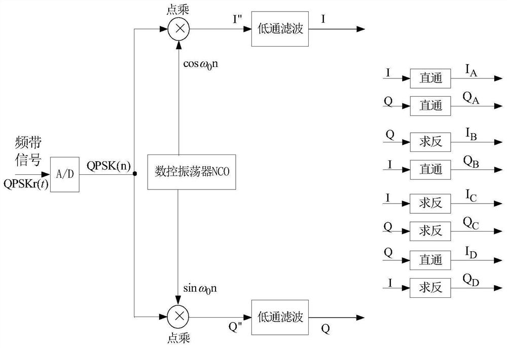
[0073] Step 1, get four pairs of intermediate signals.

[0074] refer to figure 2 , the specific implementation of this step is as follows:

[0075] 1.1) The receiving end performs AD analog-to-digital conversion on the frequency band signal:

[0076] 1.1.1) The sending end sends the QPSK modulated frequency band signal QPSKt(t):

[0077] QPSKt(t)=a(t) cosω 0 t+c(t) sin ω 0 t=cos(ω 0 t+θ)+sin(ω 0 t+θ),

[0078] Among them: t is time, a(t) and c(t) respectively represent the high and low signals of the 2-bit binary baseband signal at the sending end, ω 0 =2πf 0 is the carrier angular frequency, f0 is the local carrier frequency;

[0079] 1.1.2) The receiving end receives ...


PUM


Abstract

The invention discloses a method for demodulating a quadrature phase shift keying modulation signal, which mainly solves the problems of long time required by carrier synchronization, poor receiving sensitivity and dynamic range, small phase margin and more occupied resources in the existing method. According to the implementation scheme, after being subjected to AD analog-to-digital conversion, multiplying a frequency band signal by a pair of initial orthogonal signals generated by a numerical control oscillator at the same time, and then carrying out low-pass filtering on the result to obtain two paths of intermediate signals I and Q; performing direct connection, inversion, summation and differencing operation on the two paths of intermediate signals in sequence to obtain four pairs of result orthogonal signals; and judging the quadrant and the blind phase point of the phase difference phi between the receiving end and the transmitting end according to the values of the four pairs of result orthogonal signals, and selecting the sign bit output of the four pairs of result orthogonal signals by using the result to obtain a demodulated baseband signal. According to the invention, the time delay of signal demodulation is reduced, the receiving sensitivity and the dynamic range are improved, the phase margin is improved, hardware resources are reduced, and the method can be used for electronic navigation and communication data transmission systems.

Description

technical field [0001] The invention belongs to the technical field of signal processing, and in particular relates to a demodulation method of quadrature phase shift keying modulated signals, which can be used in electronic navigation and communication data transmission systems. Background technique [0002] The modulation signal is a signal used to change a certain parameter of the carrier signal. The quadrature phase shift keying QPSK signal is one of the modulation signals, which is used to change the phase of the carrier according to the baseband signal. It includes a pair of orthogonal binary Phase shift keyed BPSK signal. The data transmission rate of the QPSK signal is twice that of the BPSK signal, and 2 bits of information can be transmitted at the same time. If the transmission baseband signal of BPSK modulation mode is set as a(t), then the transmission baseband signal of QPSK modulation mode can be set as a(t) and c(t). The transmitting end uses the baseband s...

Claims


Application Information

Patent Timeline
Patent Type & Authority Applications(China)
IPC IPC(8): H04L27/20H04L27/22
Inventor 陈华
Owner SHAANXI CHANGLING ELECTRONICS TECH
Why Eureka
Try Eureka