Fiber reinforced polymer composite material processing equipment

A technology of fiber reinforcement and composite materials, applied in the direction of grain processing, etc., to achieve the effect of ensuring the degree of fineness

Inactive Publication Date: 2021-11-30
左文强
View PDF0 Cites 0 Cited by
  • Summary
  • Abstract
  • Description
  • Claims
  • Application Information

AI Technical Summary

Problems solved by technology

[0005] In order to solve the technical problems existing in the background technology, the present invention proposes a fiber-reinforced polymer composite material processing equipment. This device solves the problem of fiber-reinforced polymer raw material pretreatment, and at the same time performs multi-level processing on the pulverized raw material. Filtration, thereby ensuring the accuracy of raw material processing and processing. At the same time, the device has an ingenious structure, reasonable design, simple operation, strong practicability, and is suitable for wide promotion.

Method used


Image

  • Fiber reinforced polymer composite material processing equipment
  • Fiber reinforced polymer composite material processing equipment
  • Fiber reinforced polymer composite material processing equipment

Examples


Embodiment 1

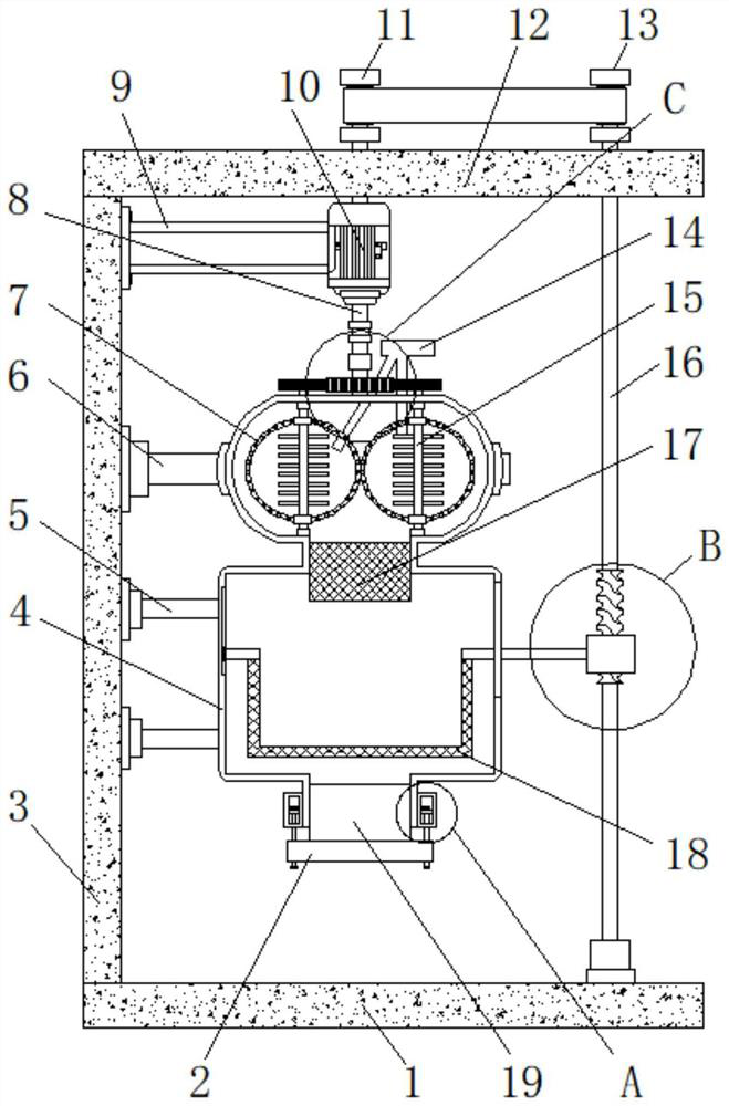
[0034] Embodiment 1: as figure 1 As shown, a fiber-reinforced polymer composite material processing equipment proposed by the present invention includes a base 1, a support column 3 is welded on the left side of the top of the base 1, and two first support frames 5 are welded on the right bottom of the support column 3 The right end of the first support frame 5 is welded with a processing box 4, the left inner wall of the processing box 4 is slidably connected with a sieve bucket 18, and the right end of the sieve bucket 18 is welded with a movable rod that penetrates and extends to the right side of the processing box 4 20. Two crushing rollers 15 are sleeved on the top of the processing box 4, and one end of the crushing roller 15 located inside the processing box 4 is rotationally connected with the inner wall of one side of the processing box 4, and the outer ring of the crushing roller 15 is welded with a crushing tank 7. First gears 24 are welded to the tops of the crush...

Embodiment 2

[0035] Embodiment 2: as figure 1 , Figure 4As shown, the top of the processing box 4 is sleeved with a feed pipe 14 that runs through and extends into the crushing tank 7, and the outer ring of the crushing roller 15 is welded with a plurality of crushing blades arranged in a rectangular array. The top of the outer ring is welded with a second support frame 6, the top of the processing box 4 is rotatably connected with a first gear 24, the top of the first gear 24 is welded with a flange tube 23, and the top of the flange tube 23 is welded with a rotating shaft 8 to support The top right side of the column 3 is fixed with a third support frame 9 by bolts, and the end of the third support frame 9 away from the support column 3 is welded with a biaxial motor 10, and the bottom output end of the biaxial motor 10 is far away from the rotating shaft 8 One end of 23 is welded, and the middle part of both sides inner walls of processing box body 4 is welded with filter case 17.

Embodiment 3

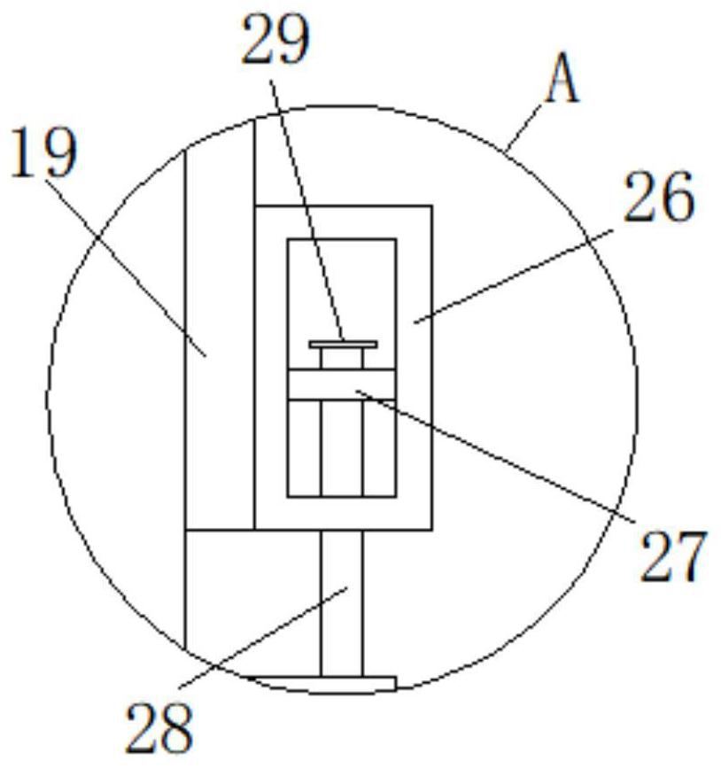
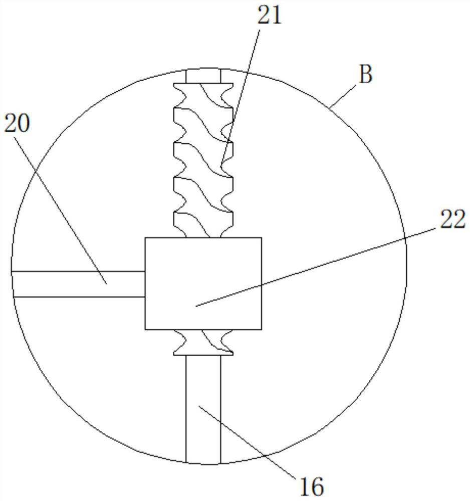
[0036] Embodiment 3: as figure 1 , Figure 6 As shown, the surrounding inner wall of the filter box 17 is welded with a fixed block 30, and one end of the fixed block 30 close to each other is welded with a filter screen 31, the top of the support column 3 is welded with a fixed platform 12, and the top output end of the biaxial motor 10 runs through and Extending to the top of the fixed platform 12, the output end at the top of the fixed platform 12 is welded with a first belt roller 11, the right side of the top of the fixed platform 12 is sleeved with a screw 16 that runs through and extends to the bottom of the fixed platform 12, the screw 16 One end located at the bottom of the fixed platform 12 is rotationally connected with the top right side of the base 1, the outer ring of the screw mandrel 16 is welded with a rotating rod 21, and the outer ring of the rotating rod 21 is threaded with a coiled tube 22, and the left side of the screwed tube 22 is connected to the Mova...


PUM


Abstract

The invention discloses fiber reinforced polymer composite material processing equipment, and relates to the field of fiber reinforced polymer composite material processing. The invention provides the following scheme aiming at the problems of non-uniform and incomplete raw material processing in fiber reinforced polymer composite material processing. The fiber reinforced polymer composite material processing equipment comprises a base, a supporting column is welded on the left side of the top of the base, two first supporting frames are welded to the bottom of the right side of the supporting column, a processing box body is welded to the right ends of the first supporting frames, a screening hopper is slidably connected to the inner wall of the left side of the processing box body, and a movable rod penetrating through and extending to the right side of the processing box body is welded to the right end of the screening hopper. According to the fiber reinforced polymer composite material processing equipment, the problem of fiber reinforced polymer raw material pretreatment is solved, meanwhile, the crushed raw materials are subjected to multi-layer filtration, the raw material treatment and processing precision is further guaranteed, and meanwhile the equipment is ingenious in structure, reasonable in design, easy to operate, high in practicability and suitable for wide popularization.

Description

technical field [0001] The invention relates to the field of processing fiber-reinforced polymer composite materials, in particular to a processing equipment for fiber-reinforced polymer composite materials. Background technique [0002] Fiber-reinforced composite material (FRP) is a composite material formed by reinforcing fiber materials, such as glass fiber, carbon fiber, aramid fiber, etc., and matrix materials through winding, molding or pultrusion molding processes. , common fiber reinforced composite materials are divided into: glass fiber reinforced composite materials (GFRP), carbon fiber reinforced composite materials (CFRP) and aramid fiber reinforced composite materials (AFRP). Large modulus, material properties can be designed, good corrosion resistance and durability, and the thermal expansion coefficient is similar to that of concrete. These characteristics make FRP materials suitable for modern structures that are large-span, towering, heavy-duty, light-weigh...

Claims


Application Information

Patent Timeline
IPC IPC(8): B02C18/10B02C18/16B02C23/10B02C23/14
CPCB02C18/10B02C18/16B02C23/10B02C23/14
Inventor 左文强
Owner 左文强
Why Eureka
Try Eureka