Welding gun, welding device and welding system
A welding device and welding torch technology, which is applied in welding equipment, auxiliary equipment, tin feeding equipment, etc., can solve the problems that welding equipment is difficult to meet, personnel cannot work at close range, and radioactive levels are high
- Summary
- Abstract
- Description
- Claims
- Application Information
AI Technical Summary
Problems solved by technology
Method used
Image

Examples
Embodiment 1
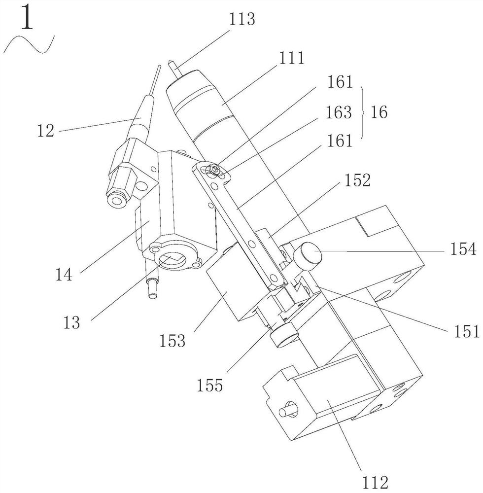
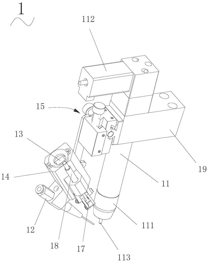
[0049] Such as figure 1 and figure 2 As shown, this embodiment provides a welding torch 1 , which includes: a welding torch body 11 , a wire feeding nozzle 12 and a camera 13 . The wire feeding nozzle 12 and the camera 13 are arranged on the welding torch body 11 .
[0050] The welding torch body 11 is a cylindrical structure, with a nozzle 111 at one end and a clamping motor 112 at the other end. A clamping mechanism and a tungsten electrode 113 are arranged inside the welding torch body 11. One end of the tungsten electrode 113 is clamped by the clamping mechanism, and the other end is provided with a clamping motor 112. One end protrudes from the nozzle 111 . The clamping motor 112 is connected with the clamping mechanism through a bevel gear transmission, and controls the clamping mechanism to clamp or loosen the tungsten pole, so as to facilitate the operation of automatically replacing the tungsten pole.
[0051] The axial direction of the wire feeding nozzle 12 is i...
Embodiment 2
[0066] Such as Figure 4 and Figure 5 As shown, this embodiment provides a welding device, including: a base 2, a wire feeding mechanism 3, an adjustment mechanism 4, and the welding torch 1 of Embodiment 1.
[0067] The adjusting mechanism 4 is arranged on the base 2 and is connected with the welding torch 1 for adjusting the position of the welding torch 1 relative to the base 2 to adjust the position of the welding torch 1 relative to the workpiece.
[0068] The wire feeding mechanism 3 is arranged on the base 2 and connected with the wire feeding nozzle 12 of the welding torch 1 through the welding wire, and is used for pulling the welding wire through the wire feeding nozzle 12 .
[0069] In this embodiment, the adjustment mechanism 4 includes a two-dimensional linear drive mechanism 41, the two-dimensional linear drive mechanism 41 is connected between the base 2 and the welding torch 1, and is used to drive the welding torch 1 to reciprocate relative to the base 2 alo...
Embodiment 3
[0079] This embodiment provides a welding system, which includes a welding machine, a control system and the welding device of Embodiment 2.
[0080] The base 2 of the welding device is arranged on a mobile trolley, and the welding machine is connected with the welding device to drive the welding device to run.
[0081] The camera 13 of the welding device is electrically connected with the control system, and is used for transmitting the real-time camera signal to the control system,
[0082] The control system is electrically connected with the welding machine and the adjustment mechanism 4 respectively, and is used to judge whether the nozzle 111 of the welding torch 1 and the wire feeding nozzle 12 are facing the area to be welded of the workpiece according to the real-time camera signal, if so, control the welding machine to start; if not, then Control the action of the adjustment mechanism 4 to adjust the position of the welding torch 1 relative to the base 2 until the no...
PUM
 Abstract
Description
Claims
Application Information
 - R&D Engineer
- R&D Manager
- IP Professional
- Industry Leading Data Capabilities
- Powerful AI technology
- Patent DNA Extraction
Browse by: Latest US Patents, China's latest patents, Technical Efficacy Thesaurus, Application Domain, Technology Topic.
© 2024 PatSnap. All rights reserved.Legal|Privacy policy|Modern Slavery Act Transparency Statement|Sitemap