Separation joint construction structure and construction method of roof ground and table top layer

A technology for separation joints and countertops, which is applied in the direction of roof covering, roof, floor, etc., can solve the problems of foundation layer damage and inconvenient construction of separation joints, and achieve the effects of saving time, improving construction efficiency and simplifying construction steps

Active Publication Date: 2021-11-30
SHANGHAI BAOYE GRP CORP +1
View PDF7 Cites 0 Cited by
  • Summary
  • Abstract
  • Description
  • Claims
  • Application Information

AI Technical Summary

Problems solved by technology

[0004] In order to solve the problem of inconvenient construction of separation joints and easy damage to the base layer, the present invention provides a construction structure and construction method of separation joints on the roof floor and the surface layer of the stand. By optimizing the supporting mold, the convenient forming of separation joints is realized. without damaging the base layer

Method used


Image

  • Separation joint construction structure and construction method of roof ground and table top layer
  • Separation joint construction structure and construction method of roof ground and table top layer
  • Separation joint construction structure and construction method of roof ground and table top layer

Examples


Embodiment 1

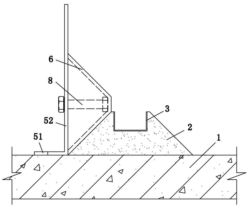
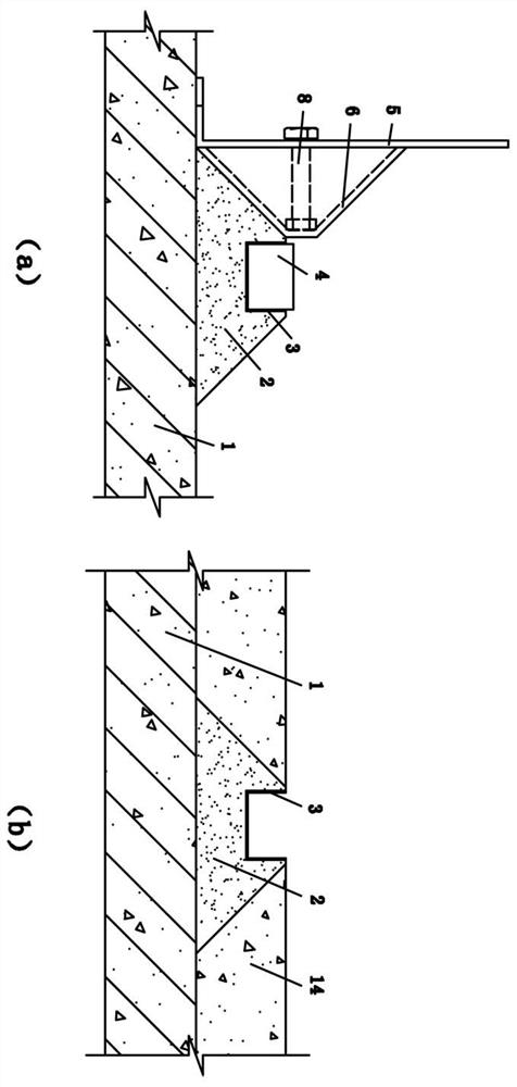
[0038] Such as Figure 1~Figure 2 As shown, a construction structure for the separation joints of the roof floor and the stand surface layer includes a base layer 1, and a mortar layer 2 is arranged on the base layer 1, and the mortar layer 2 is a layer structure formed by cement mortar. The ratio of cement mortar in the mortar layer 2 is 1:1, and the cross section of the mortar layer 2 is isosceles trapezoidal. The upper bottom of the mortar layer 2 formed by masonry has a length of 20mm and a bottom angle of 45°, and the lower bottom of the mortar layer 2 is bonded to the base layer 1.

[0039] The upper bottom surface of the mortar layer 2 is embedded with a PVC partition strip 3 to form a partition, and a sponge strip 4 is arranged inside the partition strip 3, and the function of the sponge strip 4 is to prevent blocking.

[0040] A side flat seat is provided on one side of the mortar layer 2, and the side flat seat includes an "L"-shaped vertical plate 5 and a standard ...

Embodiment 2

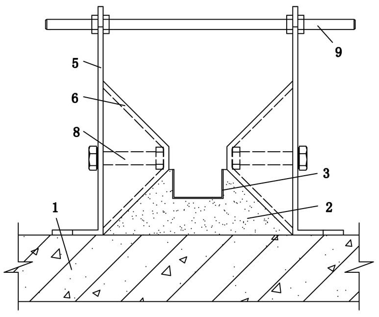
[0054] Such as Figure 3~Figure 9 As shown, this embodiment is basically the same as Embodiment 1, and the similarities will not be repeated. The difference is that: the side flat seats are arranged symmetrically on both sides of the mortar layer 2, and the side flat seats on both sides are attached to the clamping place. The mortar layer 2 is provided with a counterweight on the side flat seat. Specifically, the counterweights are distributed on the horizontal section 51, and the counterweights can be made of bricks, stones, concrete blocks and other construction materials that are easily obtained, and the horizontal section 51 is pressed by the counterweights, thereby realizing the flat seat on the opposite side. The fixing of the counterweight is not shown in the figure.

[0055] In this embodiment, the distance between the side flat seats on both sides is adjustable and connected, which can match mortar layers 2 of different sizes. Specifically, screw rods 9 are provided...


PUM


Abstract

The invention relates to a separation joint construction structure of a roof ground and a table top layer. The separation joint construction structure comprises a foundation layer, a mortar layer is arranged on the foundation layer, and the section of the mortar layer is an isosceles trapezoid; pVC separation strips are embedded in the upper bottom face of the mortar layer to form separation seams, and sponge strips are arranged in the separation strips to prevent blocking; a side leveling seat is arranged on one side of the mortar layer, the side leveling seat comprises an L-shaped vertical plate and a target plate for leveling, the vertical plate is arranged on the foundation layer, the vertical plate is detachably connected with the target plate through a bolt, the cross section of the target plate is trapezoidal, and the lower bottom surface of the target plate is attached to the vertical plate; and the waist length of the standard plate is equal to that of the mortar layer, and the planes where the two waists are located are attached. The invention further relates to a separation joint construction method of the roof ground and the table top layer. According to different areas of the roof, the ground and the stand, the mortar layer can be manually built or a side flat seat is adopted as a mold, the mortar layer is formed through one-time pouring, the construction operation of the separation joint is flexible, and the forming appearance quality of the separation joint is guaranteed.

Description

technical field [0001] The invention relates to the technical field of separation joint construction, in particular to a construction structure and construction method of separation joints on the roof floor and the surface layer of the stand. Background technique [0002] The separation joint refers to the division of the waterproof layer according to the shape, size and structural arrangement of the flat roof, leaving a joint. In order to prevent the cracking of the concrete surface in the construction of the roof, ground, and stands, it is usually necessary to set a separation joint. [0003] The traditional separation joint construction method needs to support the mold, the mold structure is single and cannot adapt to the separation joints of different sizes, and it is necessary to drill holes and insert nails on the existing base layer to fix the mold, destroy the base layer, and the process is complicated and the construction time is long. For example, in the construct...

Claims


Application Information

Patent Timeline
Patent Type & Authority Applications(China)
IPC IPC(8): E04B1/68E04D13/00E04F15/14E04H3/12
CPCE04B1/68E04D13/00E04F15/14E04F15/142E04H3/12
Inventor 张灿灿孙聪聪马志彬杜枫
Owner SHANGHAI BAOYE GRP CORP
Why Eureka
Try Eureka